

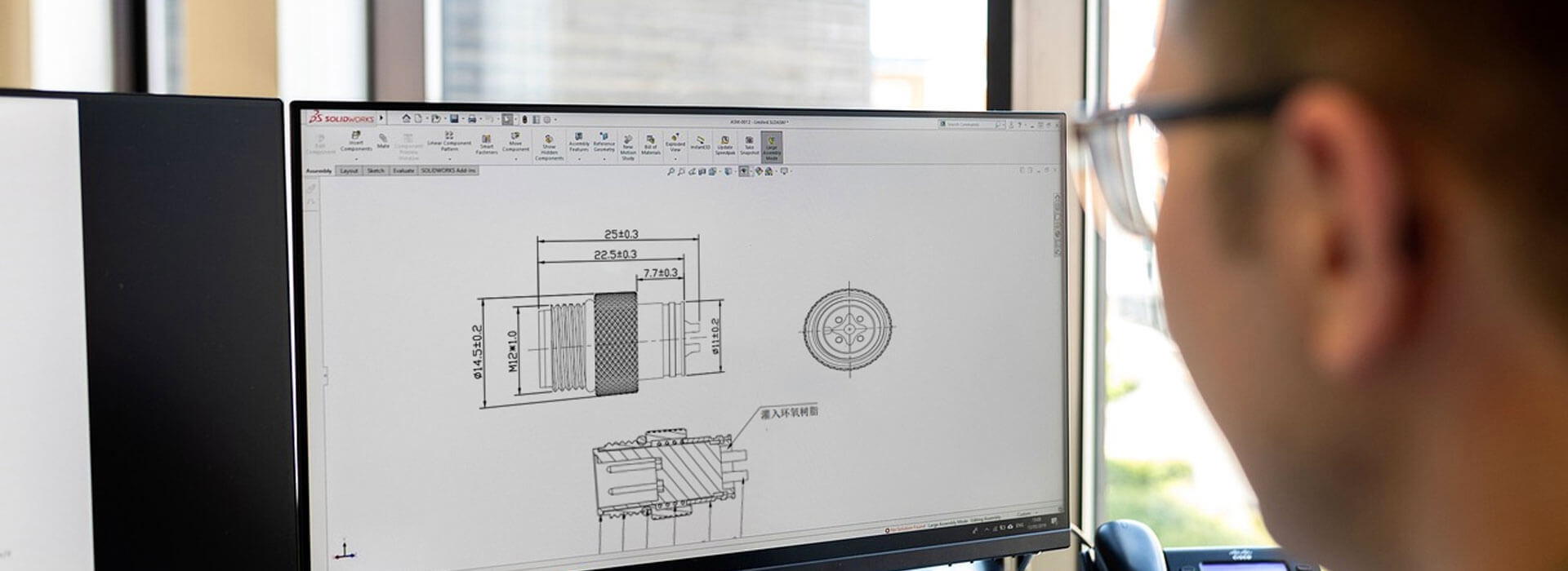
To specify the exit direction of a right-angle M12 cable connector, show its position relative to the mating key and the equipment in the installed state. State which side the drawing looks from, identify the mating receptacle, and distinguish a fixed outlet from an adjustable construction. A request for a cable that points “left” is incomplete until both parties share the same viewpoint. Agree the orientation on a drawing before approving the connector or cable assembly.
A right-angle body does not define where the cable points
The bend in the connector body describes one geometric relationship. Clocking describes another: the direction of that bent outlet around the mating axis. A connector can have the desired elbow shape and still route its cable toward a guard, an adjacent port or a surface that blocks assembly.
Think of a receptacle on a machine wall. An elbow pointing down may leave a clear route to a cable tray; an elbow pointing sideways may occupy the space needed by the next connection. These are installation examples, not guaranteed outlet positions available on any particular M12 model.
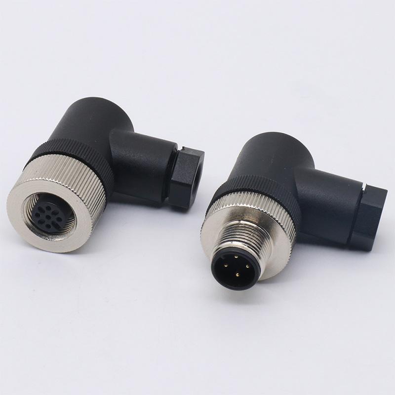
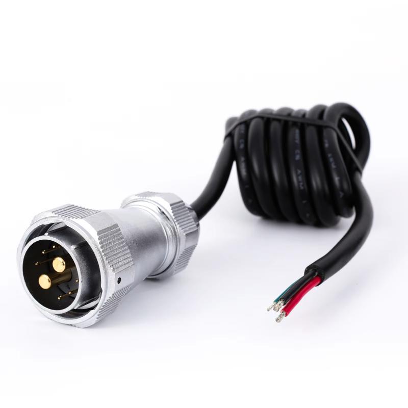
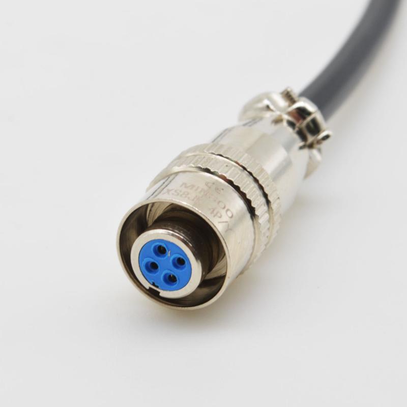
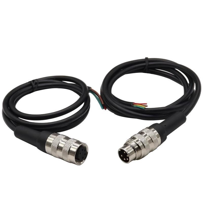
KMYD lists an M12 right-angle assembly connector. Its page establishes the offered body style, but does not settle your required clocking position or whether that position can be adjusted. Request those details for the proposed variant. A product photograph gives a useful view of the housing, while the interface and assembly drawings define the ordering requirement.
Agree the viewpoint before adding an angle
Use one reference view to describe the outlet. For example, a drawing can identify the cable connector viewed from its mating face, with the key shown at a labeled reference position. If the equipment drawing instead looks at the installed assembly from outside the enclosure, make the relationship between those views explicit.
Include the connector gender and coding in the identification, but do not use a contact number as an assumed orientation mark. The chosen part drawing should establish the key and contact references. Looking from opposite ends can reverse the apparent direction in a sketch; a photograph without a stated view can therefore be misleading even when the photographed part is correct.
- Name the object: identify the cable-side connector and the exact equipment-side mating part.
- Mark the reference: show the key or another defined datum, together with the observer's direction.
- Draw the outlet: indicate the desired cable route and its relationship to that datum.
- State the condition: show whether the connector is fully mated and the receptacle is in its final mounting position.
If an angular dimension is necessary, label its starting datum, direction of measurement and permitted tolerance. Let the supplier confirm an achievable value for the selected construction. An unlabeled arrow and a number can leave the same ambiguity as the word “left.”
Find out what can actually rotate
Do not treat the coupling nut, insert, elbow and cable as one rotating component. Ask which component, if any, permits orientation changes, when adjustment is allowed, and how the final position is retained. A locking nut that turns during mating does not, by itself, prove that the finished cable outlet can be repositioned.
Adjustability is a model feature. Phoenix Contact documents a relationship between insert orientation and cable outlet on one of its angled connectors; that is useful evidence that assembly instructions matter. It does not establish the same mechanism, adjustment range or assembly procedure for KMYD's product.
If the required position is unavailable, return to the layout decision. Evaluate another documented connector variant, a different equipment mounting orientation where permitted, or a straight exit with sufficient routing space. Do not resolve a clocking mismatch by leaving the coupling loose or twisting a finished assembly into place.
Review the space around the installed connector
An outline that clears the wall can still leave too little room for installation or service. Check the connector with neighboring plugs fitted, covers in their operating position and the intended cable supports present. Include access to the coupling, not only clearance around the elbow.
| View | What it should reveal | Decision it supports |
|---|---|---|
| Mating-face reference | The key, observer direction and required outlet position | Whether the proposed clocking matches the drawing |
| Installed side view | Housing projection, nearby surfaces and cable departure | Whether the assembly fits the available depth |
| Service-access view | Adjacent connectors, hand or tool access, and the removal route | Whether the connection can be assembled and replaced |
Use the specified cable's installation limits when reviewing the first bend after the connector. Those limits depend on the actual cable and duty. A neat-looking bend in a rendering is not evidence of an acceptable bend radius or repeated-motion capability.
Make the approved orientation repeatable
Ask for the offered connector reference and the agreed view on the same controlled drawing. For a cable with two angled ends, define each end separately and show their relative orientation; laying the cable in a different position should not change the meaning of the drawing.
Check the first assembly against the intended receptacle or a documented fixture. Record the drawing revision and a photograph from the defined view. Keep any deviations visible in the approval record, especially when a substitute connector changes the elbow envelope or orientation choices.
The next useful step is a marked installation sketch showing the receptacle, key reference, cable direction and surrounding obstruction. With those details, the supplier can confirm a specific configuration instead of interpreting a general request for a right-angle cable.
Technical example: Phoenix Contact's model-specific angled-connector mounting notes. Its assembly features are not KMYD specifications.



 Tel: +8619924482730
 Email: info@kmydconnector.com
 MP/WhatsApp: +8619924482730
 Manufacturer Address:Baoan District, Shenzhen City, Guangdong Province,China