
Small Installation Footprint
Evaluate connector body, panel space and cable routing for compact equipment layouts.
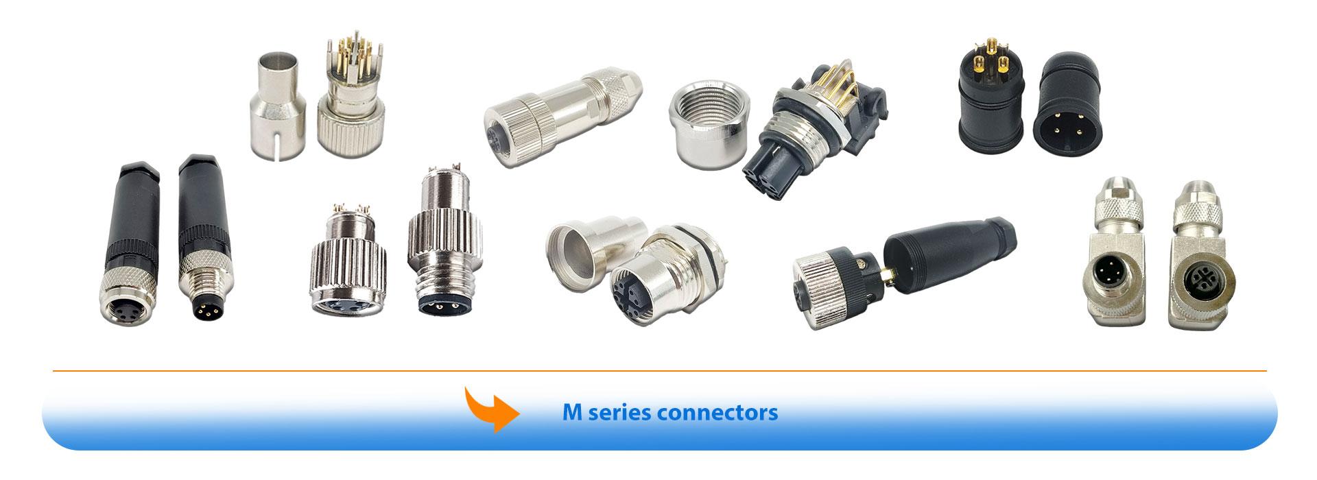
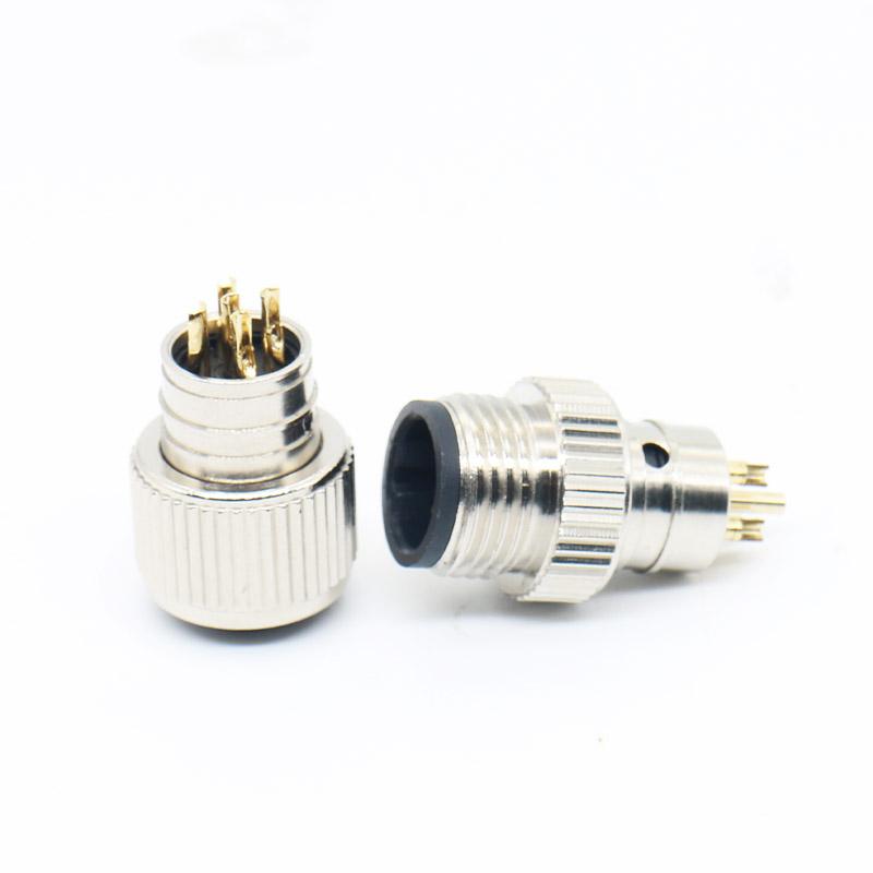
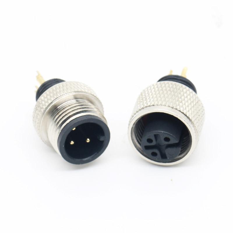
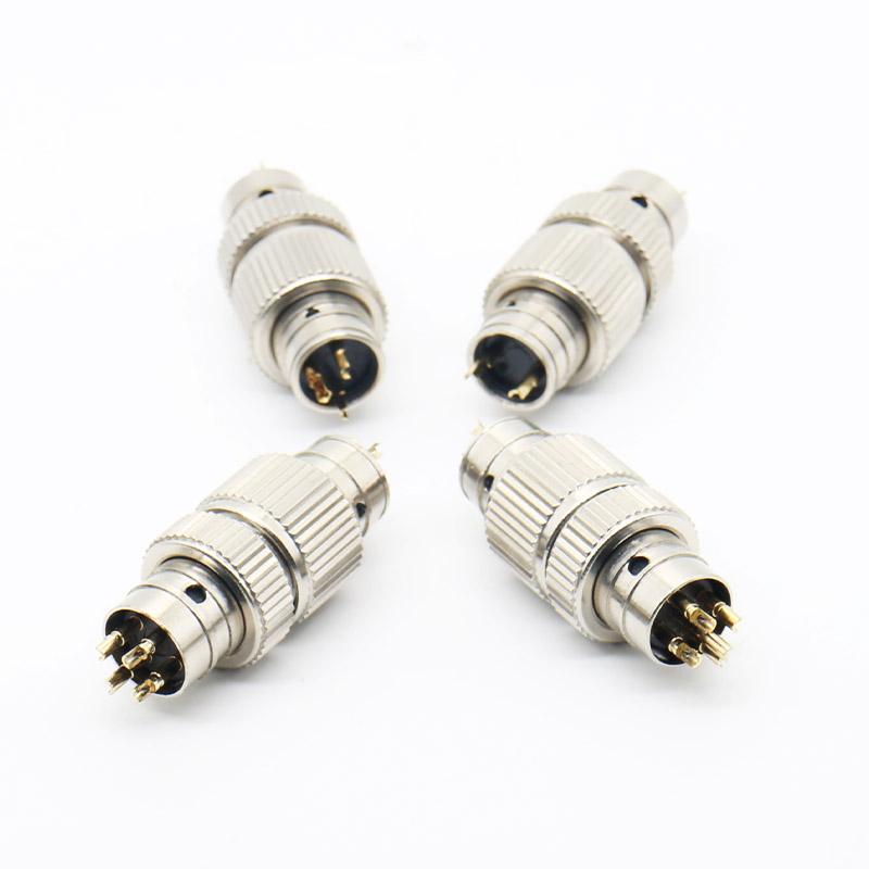
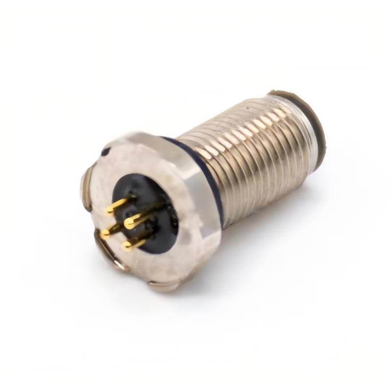
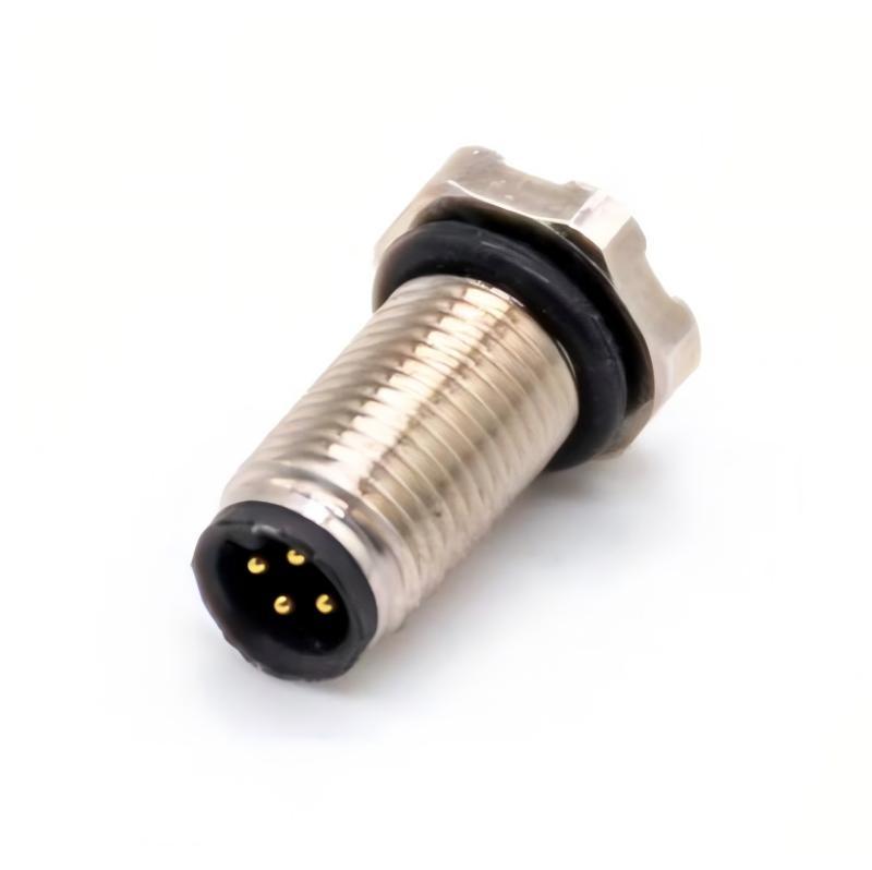
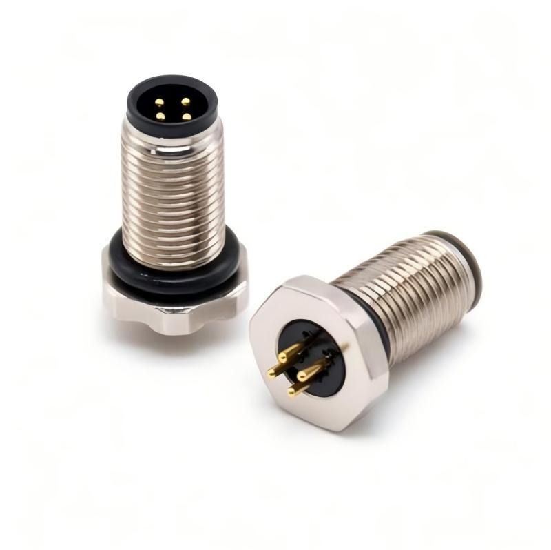
M5 circular connectors provide a compact connection option for miniature sensors, measurement devices and automation equipment. KMYD supports connector matching, panel and cable configurations, and custom cable assemblies.
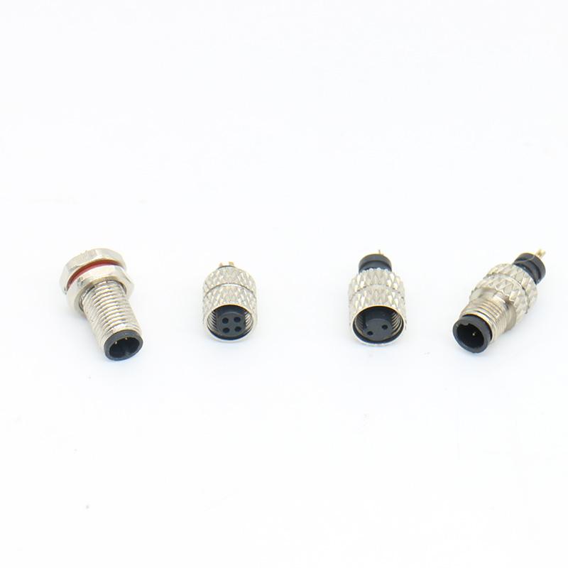
Evaluate connector body, panel space and cable routing for compact equipment layouts.
Verify pin layout, gender, mounting method and mating direction before production.
Specify cable length, wire construction, pinout, labels and opposite-end termination.
Confirm fit, wiring and assembly details with an approved specification or sample.
Review the connector body, cable outlet and bend direction together rather than checking thread size alone.
A pre-assembled M5 cable can reduce on-site termination work and wiring mistakes.
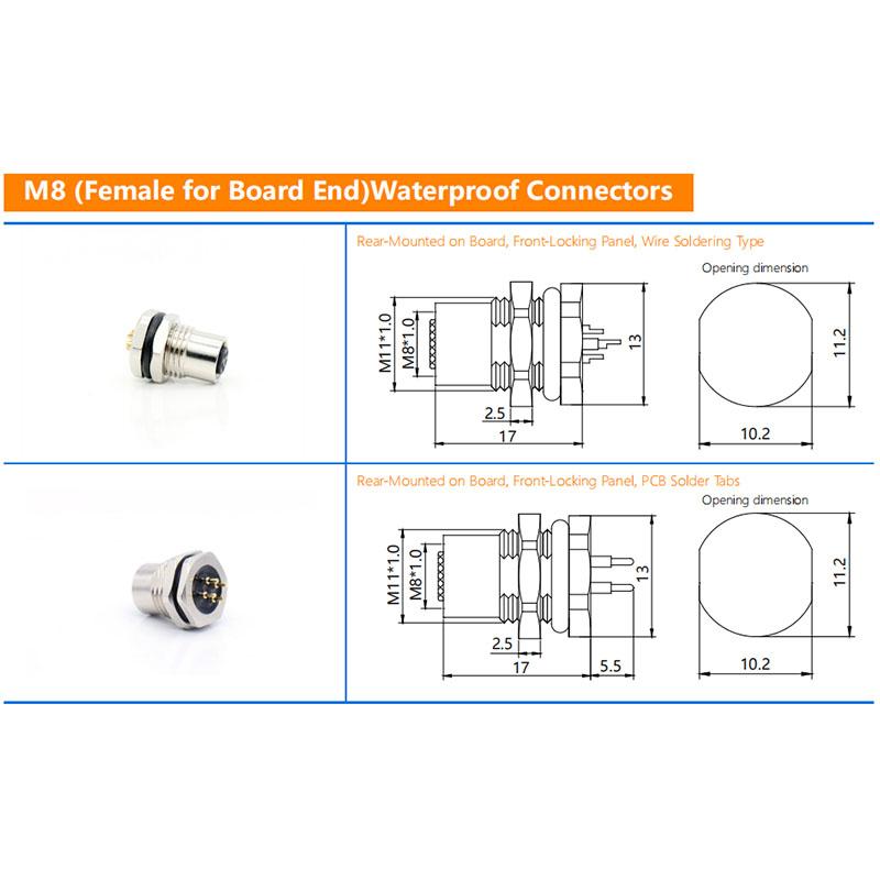
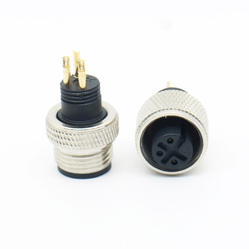
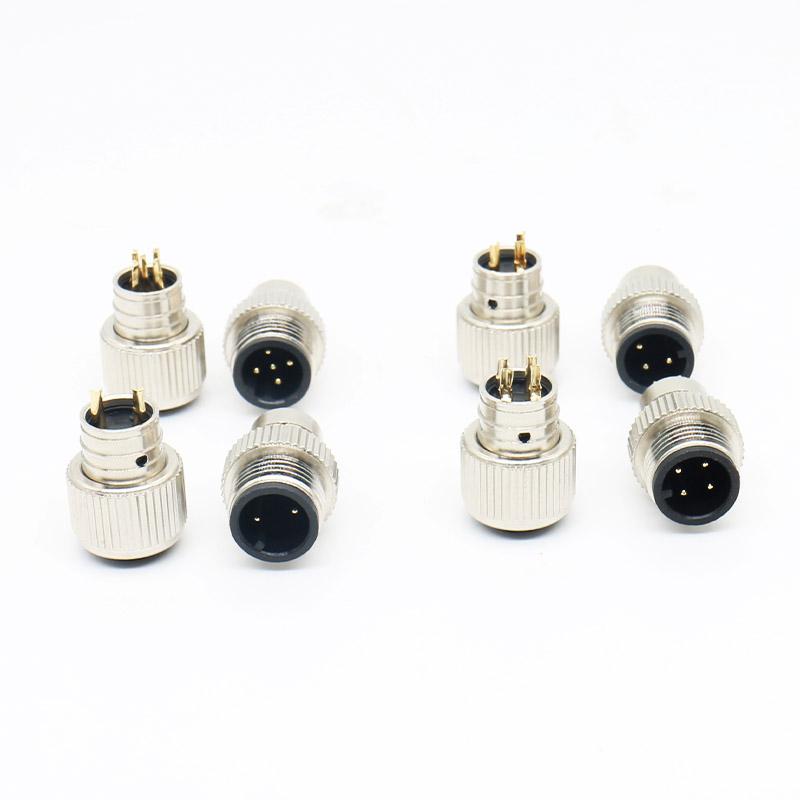
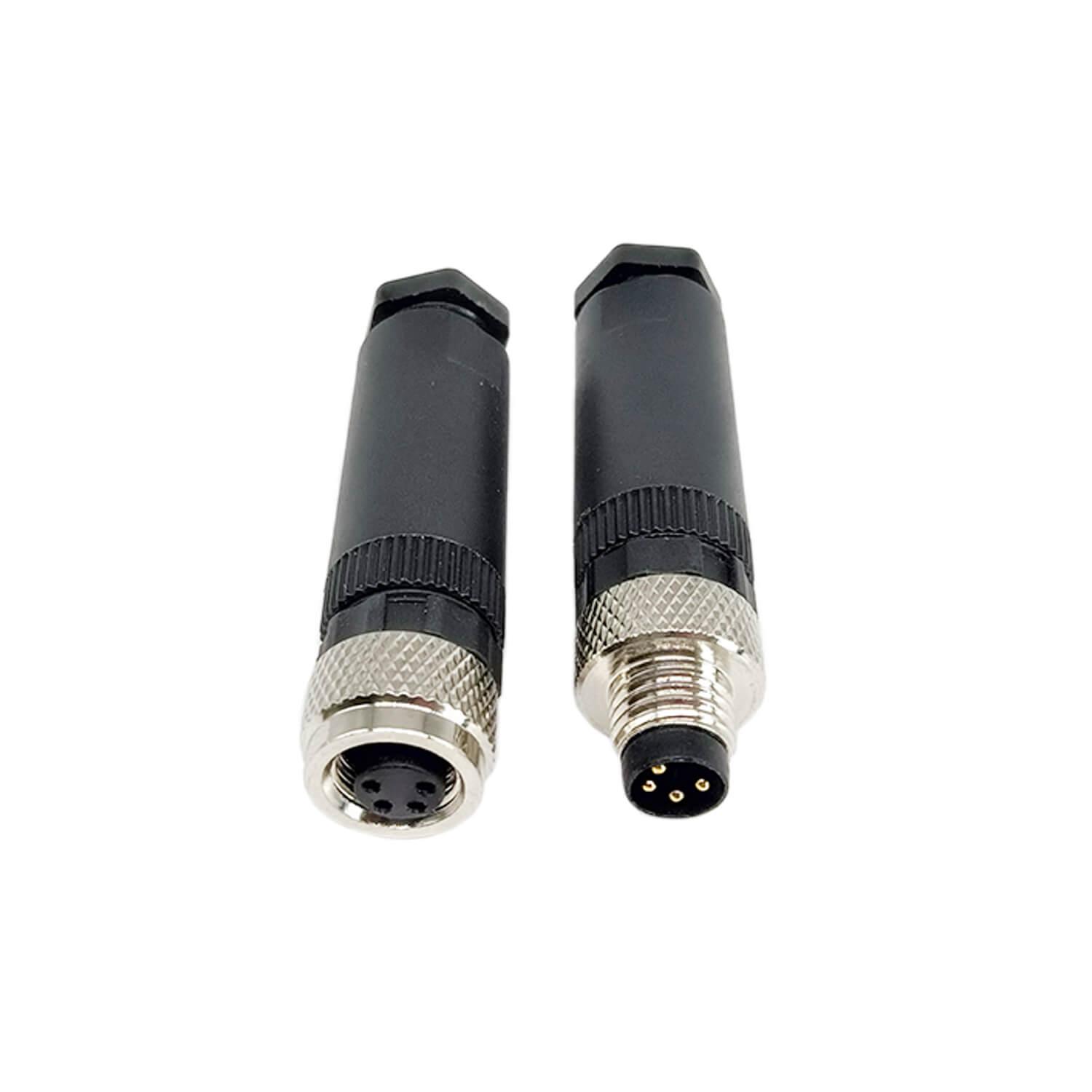
Use front, side and rear photos, dimensions, pin layout and a mating sample for identification.
Lock the approved pinout, cable specification, dimensions and labels before batch scheduling.
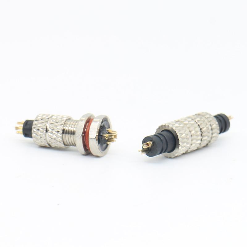
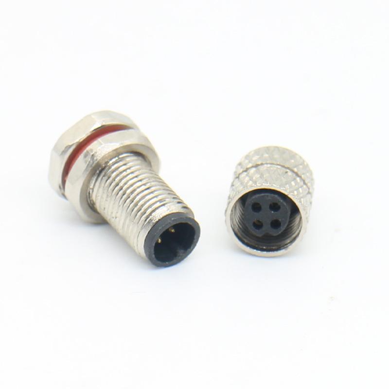
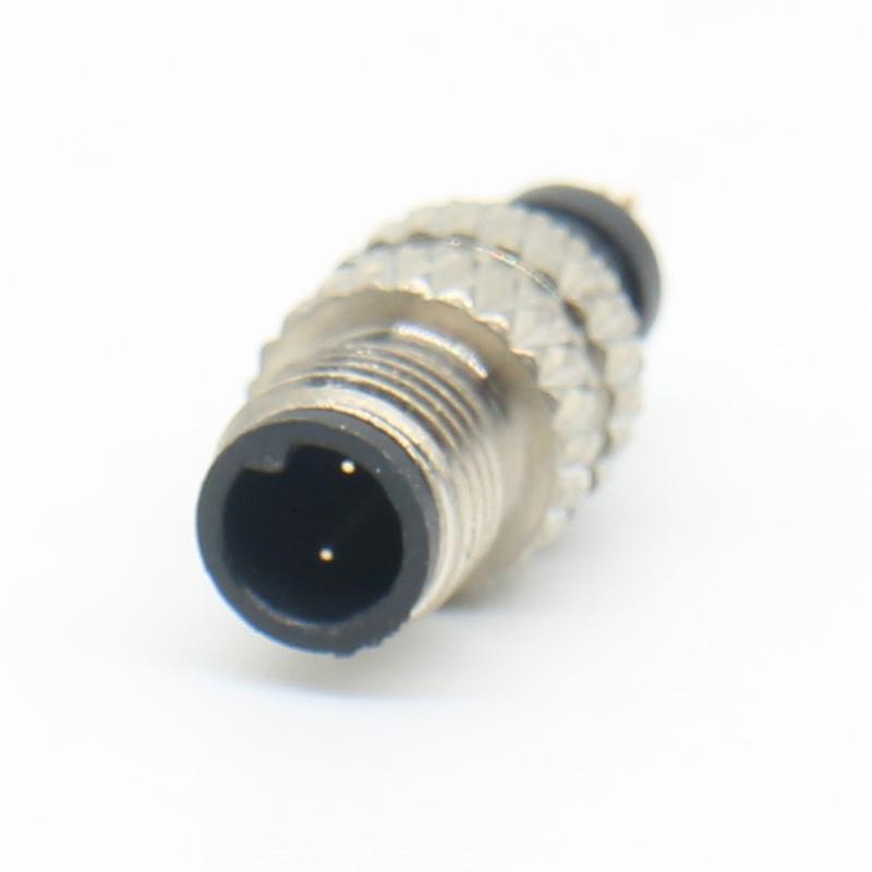
 MOQ MOQ |
>200 |
| Number Of Cores |
2-4Pin |
 Contact Diameter(mm) Contact Diameter(mm) |
0.5mm |
| Temperature Range |
-20℃~+95℃ |
 Termination Termination |
Solder/Panel Mount |
 Rated Current(A) Rated Current(A) |
2A |
| Rated Voltage(Ac.V) |
250V |
| Test Voltage(Ac.V)1Min |
800V |
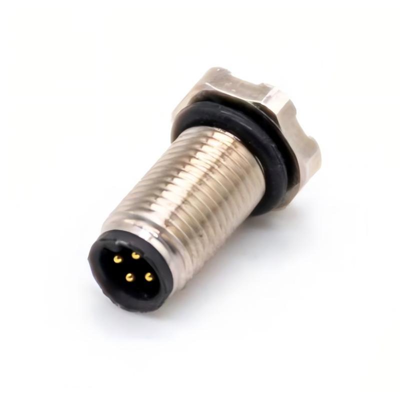
| MOQ |
>200 |
| Number Of Cores |
4 Pin |
| Contact Diameter(mm) |
0.6mm |
| Temperature Range |
-25°C ~ +80°C |
| Termination |
Solder |
| Rated Current(A) |
1A |
| Rated Voltage(Ac.V) |
60V |
| Test Voltage(Ac.V)1Min |
500V |
Interface: pin count, pin layout, key position and gender.
Installation: cable or panel mount, outlet direction and available clearance.
Cable: wire construction, length, flexibility, jacket and opposite end.
Environment: moisture, dust, vibration, temperature and mating frequency.
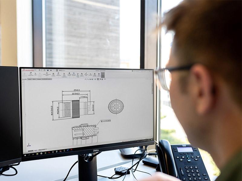
Pin position, housing, thread and mating details are checked against the approved requirement.
Termination, insulation, cable outlet, labels and finished dimensions are reviewed during production.
Continuity and other agreed checks help confirm the finished assembly before packing.
M5 connectors are commonly considered where installation space is limited and a compact circular connection is needed for sensors, measurement or control devices.
No. Pin arrangement, keying, gender, mounting and electrical design can differ. Confirm the mating interface and drawing.
Yes. Provide the connector interface, pinout, cable type, length, opposite end, quantity and operating conditions.
Send clear mating-face and side photos, dimensions, pin layout, equipment application and the matching part if available.
Share your interface, installation space and wiring requirement for factory evaluation.


 Tel: +8619924482730
 Email: info@kmydconnector.com
 MP/WhatsApp: +8619924482730
 Manufacturer Address:Baoan District, Shenzhen City, Guangdong Province,China