

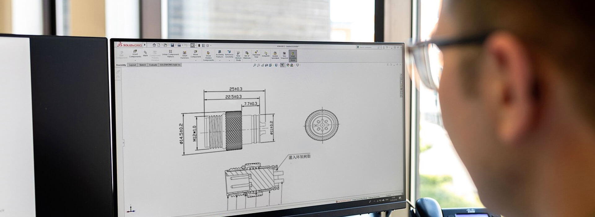
A useful custom M12 cable assembly inquiry defines both ends, the wiring between them, the cable, and the conditions it will face. Send the mating-part references, connector coding and contact count, a wiring drawing, finished length with measurement points, and installation requirements. Add quantities and the documents needed for sample approval. These details let the supplier propose a specific build and identify unresolved requirements before the quotation becomes a purchase order.
On this page
Describe two endpoints, not just “an M12 cable”
Begin with the devices the cable will connect. An assembly may have M12 connectors at both ends, an M12 connector and an open lead, or different interfaces at opposite ends. Give each end a name, such as End A at the sensor and End B at the control cabinet. Use those names consistently on the quotation, drawing and inspection record.
Equipment connection
Mating part reference, coding, contact arrangement, plug or socket, and straight or angled exit.
Cable and wiring
Cable specification, finished length, conductor mapping, shielding and identification.
Destination connection
Second mating interface, panel mounting requirements, or the preparation of an open end.
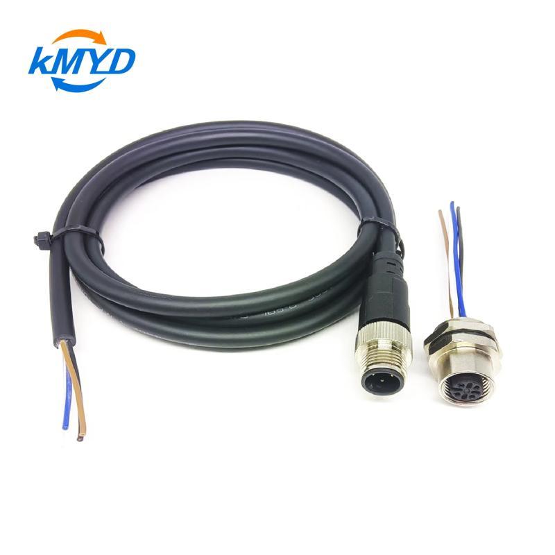
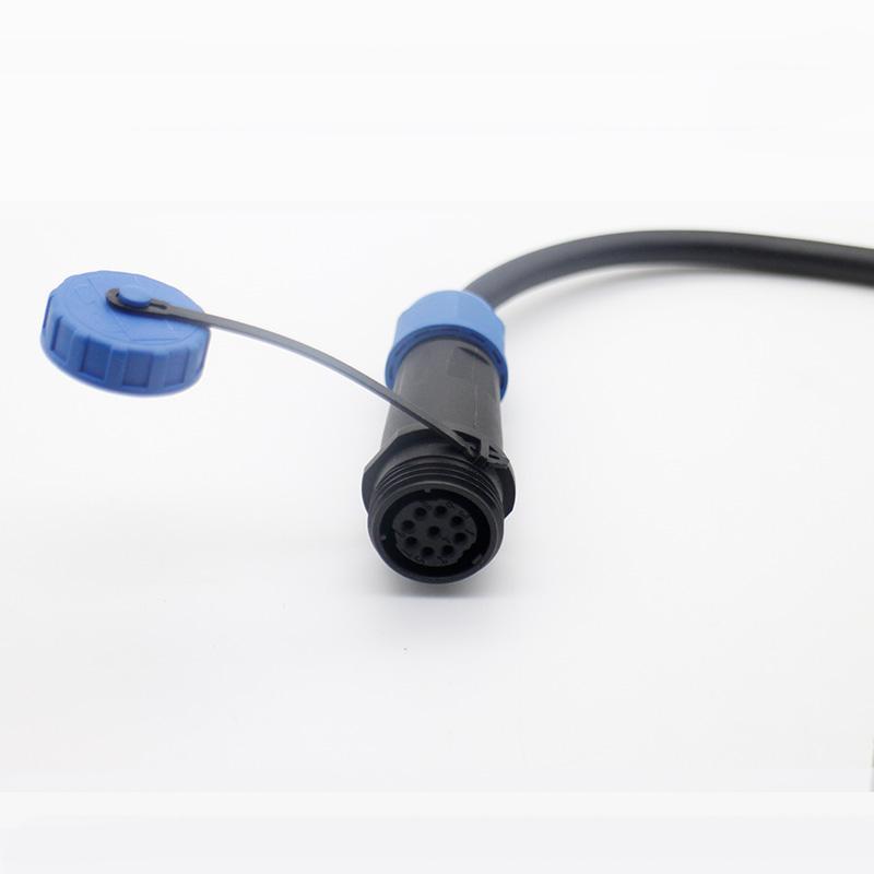
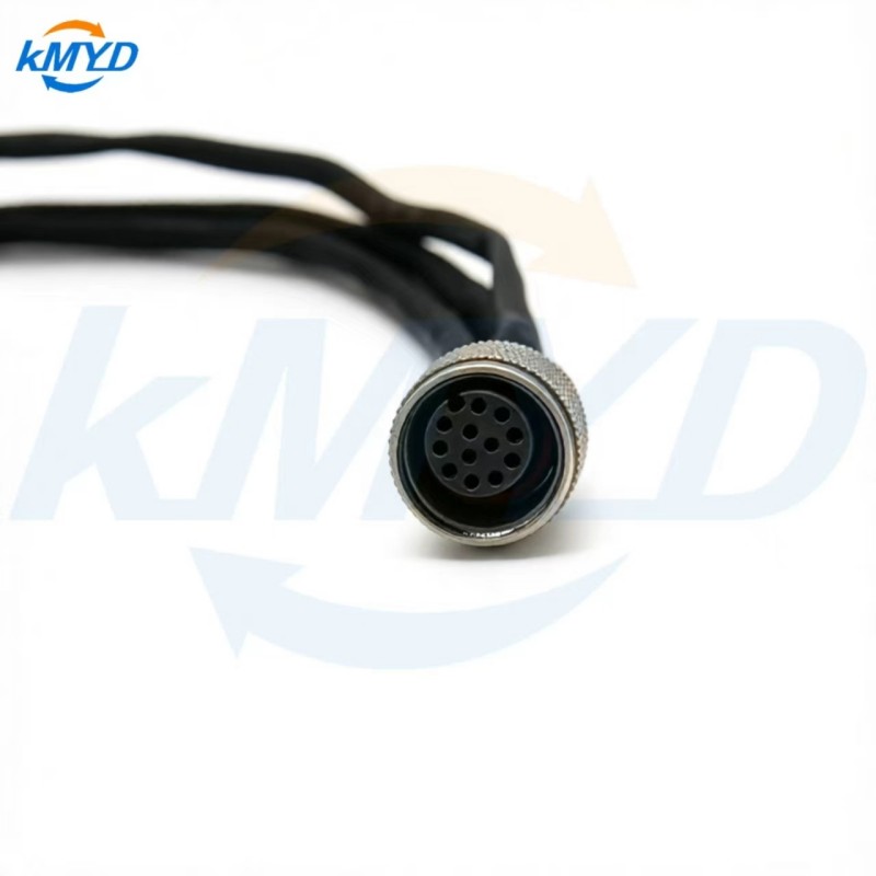
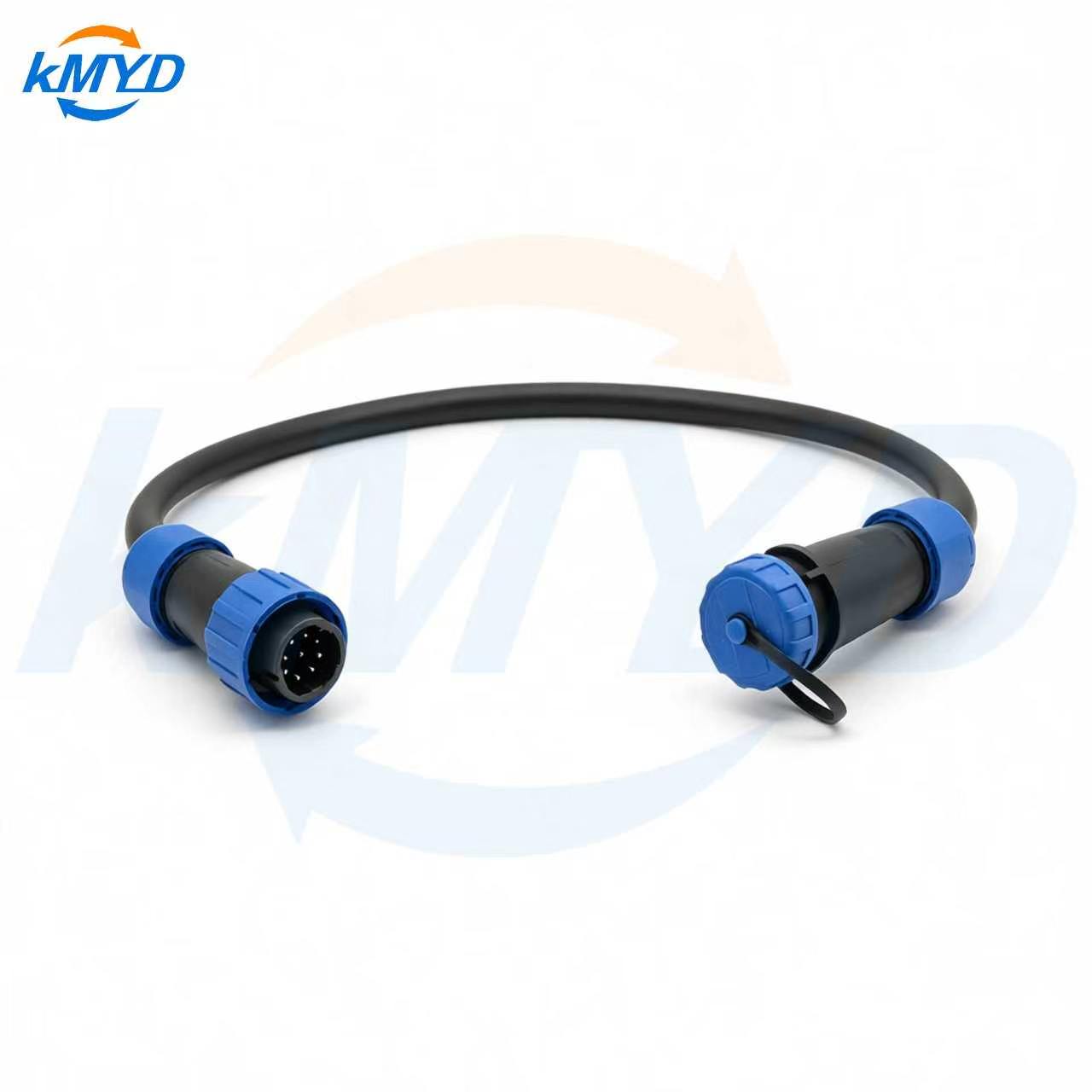
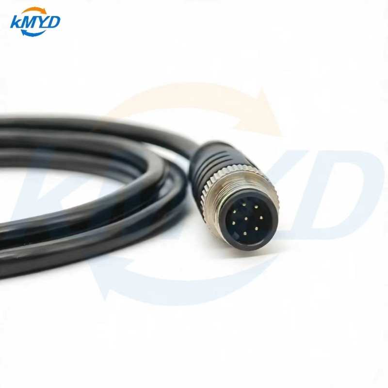
A photograph is useful for identifying an existing part, especially if the label is difficult to read. Include the mating face and a side view. For order approval, obtain the actual part reference and drawing. Contact count alone does not define the coding, pin assignment or intended interface.
Specify the required coding separately at each M12 end. A product listing with several coding options is a choice to resolve, not evidence that a single connector fits every option. Ask the supplier to identify exactly which variant is included in the quotation.
Put the requirements on one specification sheet
Separate what the project requires from what the supplier offers. This makes alternatives visible: a proposed cable jacket, connector body or termination can be reviewed without losing the original requirement. Leave an unresolved field clearly marked rather than filling it with a value copied from another M12 product.
Swipe to view all columns →
| Field | What to provide | What to confirm in the offer |
|---|---|---|
| Interfaces | End A and End B mating references, coding, contacts and orientation | The exact proposed connector variant at each end |
| Wiring | Contact-to-contact or contact-to-wire map, shield connection and unused contacts | A drawing with an identified viewing direction and revision |
| Cable | Conductor size, outside diameter, shielding, jacket and installation conditions | The proposed cable specification and any differences |
| Length | Finished length, reference points, tolerance and open-end preparation | The same measurement method on the assembly drawing |
| Operating conditions | Electrical duty, signal interface, temperature, motion and exposure | Documented suitability for the offered configuration |
| Delivery and approval | Sample and production quantities, labels, packaging and inspection documents | Drawing approval, sample checks and quoted delivery terms |
KMYD's M12 custom cable product page lists length, shielding, wire gauge and pin assignment among the available customization topics. Use those as discussion fields, then request confirmation for the particular configuration being ordered. A description of available options is not a completed specification.
Make the wiring drawing unambiguous
Label the connector ends and show how the contacts are viewed. Looking into a mating face and looking from the termination side are different references; a drawing must identify which one it uses. Mark the key position and include the connector references so the contact numbering can be checked against their documentation.
For an open-ended cable, list the required wire identification and preparation. State whether the ends are to remain unstripped, be stripped, or receive specified terminations. Give the applicable lengths and identify any conductor that must remain unconnected. Do not assume that a wire color alone establishes its function.
Define the intended treatment of the shield where one is required. Ask for that arrangement to appear on the drawing and in the proposed inspection plan. A product photograph cannot show the internal shield connection, and the word “shielded” alone does not settle the details needed for your equipment.
Show the route the cable must follow
Measure the installed route, including access around the connector, strain relief and bends. Then define where the finished length starts and ends. An overall tip-to-tip dimension and a cable-only dimension can describe different assemblies, even when the same number appears on a quotation.
For an angled connector, show the required exit direction relative to the mating key and nearby equipment. Review the fully mated assembly, not just the cable laid flat on a desk. If an enclosure lid, adjacent socket or machine guard restricts access, include that condition in the route drawing.
Identify whether the cable stays fixed or moves during operation. Where repeated movement is involved, provide the motion, bend and service requirements and ask for a suitable cable specification. Do not infer flex life from the jacket material name or from the fact that a cable feels flexible.
Describe moisture, dust, cleaning agents, oils, sunlight and temperature as applicable. Ask which conditions the offered complete assembly is documented to withstand. For sealing, specify whether the requirement applies while mated, unmated, or both, and include the panel interface when the assembly passes through an enclosure.
Add the constraints that change the proposed build
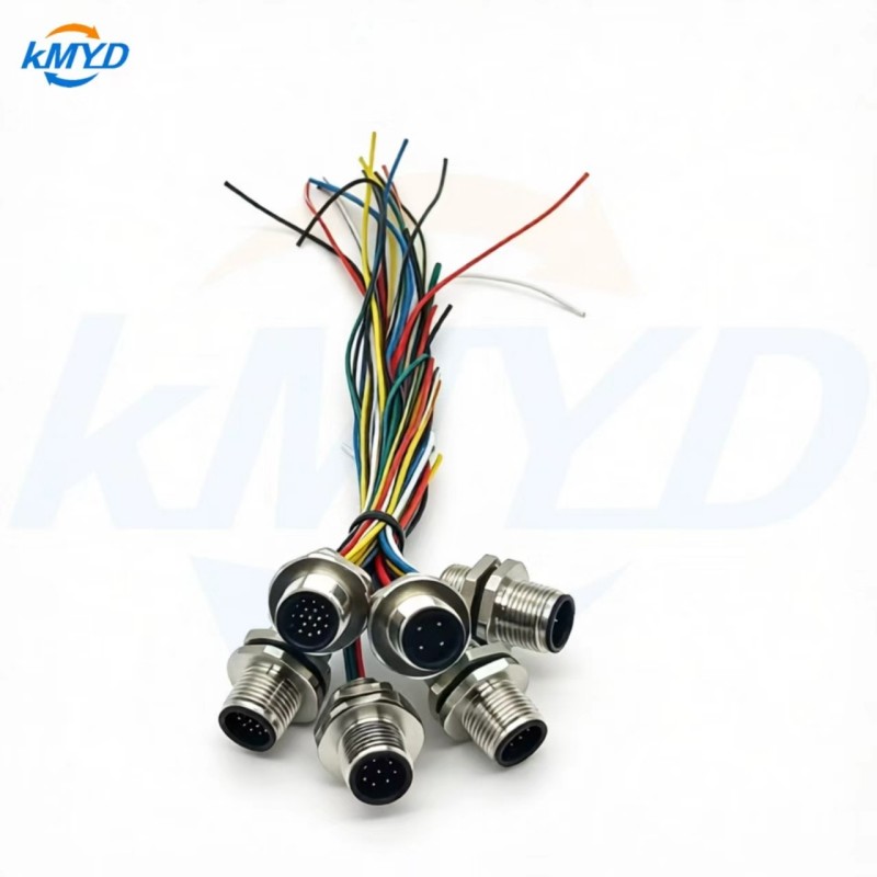
If one end mounts to a panel, provide the enclosure drawing, panel thickness, mounting direction and available space on both sides. KMYD's pre-wired M12 panel connector page is a relevant starting point for this configuration. Confirm the actual mounting thread, hardware and cutout on the offered drawing before preparing the enclosure.
State the circuit's voltage, current and signal requirements separately. Include relevant starting or transient conditions. Request the connector and cable limits for the quoted build rather than accepting a general series value. For a data connection, identify the required equipment interface and performance requirement; a pin count is not a substitute for that information.
Add identification and handling requirements before the sample is made. Specify end labels, cable marking, any project part number and packaging needed to prevent confusion between similar assemblies. Ask the supplier to list exceptions or proposed alternatives against the requirement sheet so they can be resolved explicitly.
Approve the sample against the agreed build
Agree the acceptance checks with the supplier before ordering the sample. Depending on the project, these may cover part identification, dimensions, fit, wiring continuity and the required electrical or environmental evidence. Specify the applicable test method and limits where testing is required; an inspection list should not imply that every check has already been performed.
- Check the documents: the quotation, assembly drawing and sample label identify the same configuration and revision.
- Check the fit: both ends mate with the intended equipment and remain accessible in the installed position.
- Check the route: the length, exit direction and cable clearance match the agreed drawing.
- Check the wiring record: the reported contact mapping and required test results correspond to the supplied sample.
Keep the accepted drawing and sample record with the purchase order. For repeat production, reference that build and require proposed substitutions to be reviewed. That gives both buyer and supplier a clear basis for deciding whether the next delivery is the same assembly.


 Tel: +8619924482730
 Email: info@kmydconnector.com
 MP/WhatsApp: +8619924482730
 Manufacturer Address:Baoan District, Shenzhen City, Guangdong Province,China