

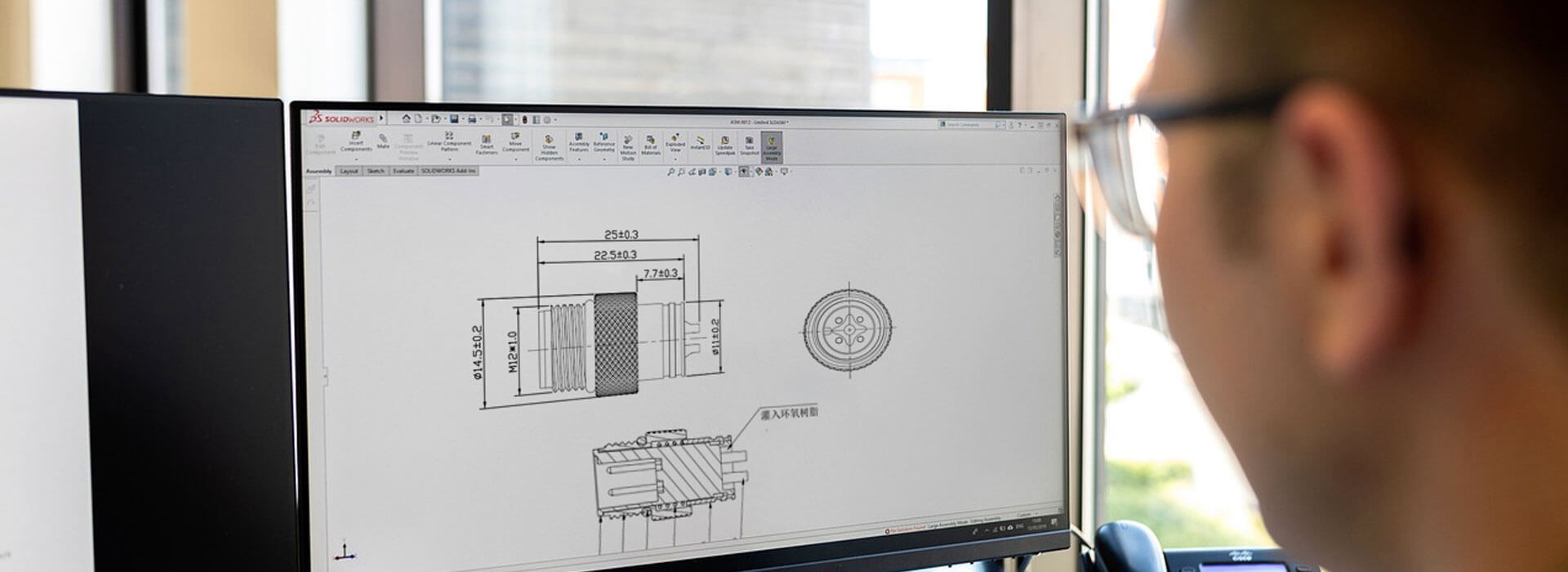
For a conventional two-wire, high-speed CAN network, define termination at the two physical ends of the main bus before specifying custom cable assemblies. Then identify what supplies each termination: equipment circuitry, a component built into a cable, or a separate terminator. A connector at the end of an individual cable is not necessarily at the end of the bus. That distinction determines whether adding a terminating component completes the design or duplicates one already present.
Find the ends on the network, not on the cable photograph
Consider a linear bus running past four connection locations, named A, B, C and D in physical order. The main cable path begins at A and ends at D. B and C connect along that path. In this example, the termination positions are A and D; the presence of a connector at B or C does not create another main-bus end.
Now consider a short replacement assembly between two adjacent locations. It has two connector ends, but it may occupy the middle of the network. Calling it a “CAN cable with termination” leaves the reviewer unable to decide whether its internal components belong at that position.
Example decision: an assembly containing a fixed terminating network near A cannot automatically replace a plain connecting assembly between B and C. Even if the interfaces fit, the substitution can add termination in the middle while leaving the intended end configuration unresolved.
Show the main path and any short node connections on a network sketch. A branch junction or service connector does not turn every outgoing leg into a separately terminated bus. The network designer must confirm the permitted topology and node connections. This discussion concerns the conventional high-speed physical layer; other CAN physical layers need their own rules.
Assign each end to one documented implementation
For each physical bus end, identify the planned termination implementation and where it resides. The equipment manual may describe a built-in switchable termination. Another design may use a removable accessory or a terminating network supplied within the cable assembly. Record the selected arrangement so the buyer can see what must be ordered and the installer can see what must be enabled.
Identify the device and its required setting. Check whether the termination is fixed or configurable.
Identify the exact assembly variant, the component arrangement and the physical end where it belongs.
Identify the part, installation position and who includes it with the equipment or cable delivery.
A purchasing gap can arise when the equipment supplier expects a terminator in the harness, while the harness supplier expects it inside the device. The opposite misunderstanding creates duplicates. Put the agreed implementation against A and D on the same sketch, then ask each supplier to confirm only the portion it provides.
Termination reduces reflections associated with the ends of the transmission line. Texas Instruments describes both standard and split termination arrangements for high-speed CAN. Those are circuit-design choices; a buyer should preserve the approved network rather than substitute a convenient resistor solely because it fits inside a connector shell.
Check what remains when a device is removed
If the terminating network sits inside a removable end device, disconnecting that device can remove the termination too. Decide whether the remaining network is intended to operate in that service state. If it is, the system design must provide an appropriate arrangement for that state; a loose connector cover does not supply an electrical function merely by closing the port.
Check temporary equipment as well. A commissioning interface or diagnostic adapter may have its own selectable termination. Its setting needs to match the approved network while it is connected. Successful communication with the service tool attached can otherwise conceal a configuration that changes as soon as the tool is removed.
Use the A-to-D example to review a replacement. If D is exchanged, confirm whether the new device includes the same end termination or expects an external one. The replacement can retain the same mating connector while changing that responsibility. Keep this decision with the equipment configuration, where maintenance staff can find it.
Make the cable variant recognizable before installation
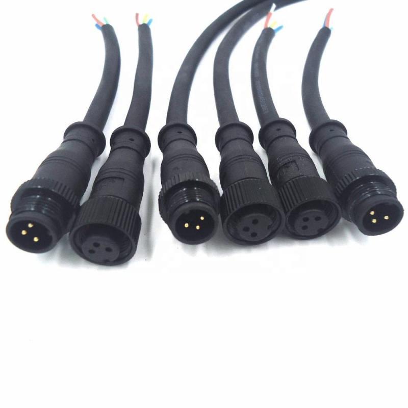
If the cable contains termination, show that circuit explicitly in its assembly definition, including its location relative to the named cable ends. Use the component network and limits selected by the system designer. If the cable contains none, state that too. “Wired for CAN” is too broad to distinguish these two supplies.
Give terminated and unterminated variants distinguishable part identities when they may be handled together. Identify the intended network position on the installation instructions. That lets a technician choose the correct replacement without opening a connector to discover whether a component is hidden inside.
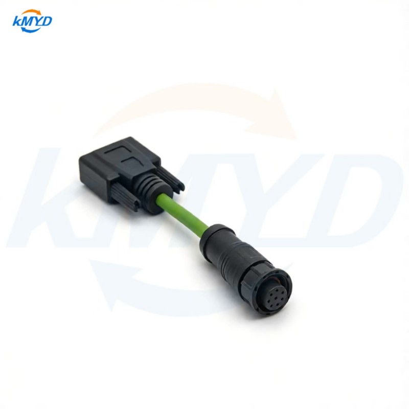
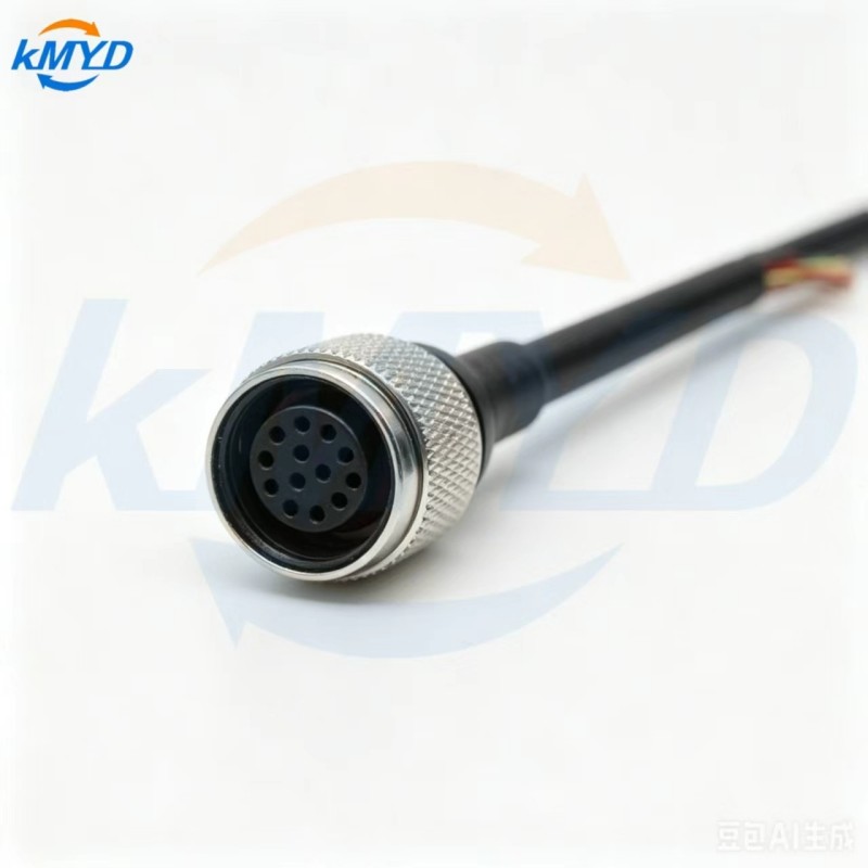
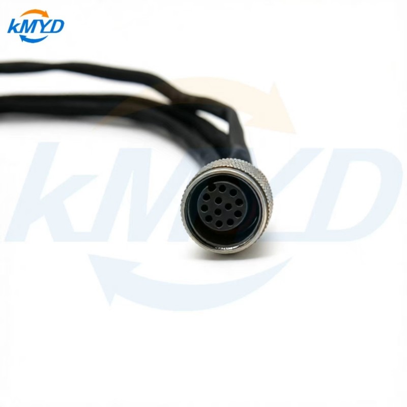
KMYD's M16-to-DB9 custom adapter can be discussed as an interface configuration, but its shape does not make it a qualified CAN assembly. For it, or a custom circular cable, the equipment interface, cable construction and required network performance still need confirmation. No universal numbered DB9 or circular-connector pinout is supplied here.
Inspect the finished network in its intended state
Close the termination review with the system assembled as it will operate: normal devices connected, required settings selected, separate accessories installed and temporary tools accounted for. Compare that configuration with the marked network sketch. An isolated cable inspection cannot see a termination that exists inside another supplier's device.
Have the responsible engineer define the electrical checks for that configuration. A simple resistance observation can support an investigation, but connected electronics, switch states and the selected terminating network affect its interpretation. Avoid turning one convenient meter reading into a substitute for the equipment's commissioning procedure.
The practical handover is a short location record: A is terminated by this identified item; D is terminated by that item; the intervening cable variants contain the components shown on their drawings. With those decisions explicit, the next replacement can preserve the network instead of merely matching its connectors.
Physical-layer background: Texas Instruments, line-termination discussion in section 4.5; Kvaser CAN physical-layer and bus-termination overview. Follow the current documentation for the actual equipment.


 Tel: +8619924482730
 Email: info@kmydconnector.com
 MP/WhatsApp: +8619924482730
 Manufacturer Address:Baoan District, Shenzhen City, Guangdong Province,China