


Insulation resistance and dielectric withstand assess different properties of custom cable assemblies. An insulation-resistance test measures how strongly the specified insulation path resists electrical leakage under defined DC conditions. A dielectric-withstand test checks whether that path sustains a specified electrical stress for the required period without exceeding its failure criteria. An order that requests only “hipot tested” should identify which assessment is required, where it applies and what constitutes an acceptable result.
Read the quantity next to the result
Imagine receiving two reports for the same cable. One gives a resistance in megohms. The other lists an applied voltage, duration and current limit. Those reports are not necessarily inconsistent. They may describe different questions about the insulation between the same circuits.
- Insulation resistance
- Dielectric withstand
- How much resistance does the selected insulation path present under the specified measurement conditions? Acceptance normally requires a stated minimum resistance.
- Does the selected insulation path withstand the prescribed stress throughout the test? Acceptance concerns the defined leakage/current limits and breakdown or arcing criteria.
Cirris distinguishes these assessments in its testing guidance. Its insulation-resistance description uses DC voltage and a minimum-resistance decision. Its dielectric-withstand description allows AC or DC procedures and uses current and transient-failure criteria. The applicable assembly requirement must select the actual method; “high voltage” alone does not identify it.
Resistance and current are related, but converting one isolated reading with Ohm's law does not make the two procedures interchangeable. The voltage waveform, application period, charging behavior and way the tester detects an event can differ. Compare the complete test definitions before deciding whether one report satisfies the other requirement.
Decide which circuits should be isolated
An insulation test needs a defined pair of electrical boundaries. It may concern one circuit against another, a group of conductors against a shield, or another arrangement specified by the design. The fixture and test program must reach those boundaries without silently leaving out the relevant path.
Use the assembly's actual circuit to identify intentional connections. A cable containing a resistor, suppressor, indicator or other component cannot always be treated as a bundle of isolated wires. A deliberate path might explain a measured current; it might also make a proposed test inappropriate for that component. The test engineer needs that information before deciding how the assembly is assessed.
Confirm the condition of the test item. A standalone passive lead and the same lead connected to equipment are different test configurations. Connected electronics can introduce extra paths and may be unsuitable for the intended stress. Testing belongs with competent personnel using an approved procedure, suitable equipment and the required safeguards; the purchase description should not invite improvised high-voltage checks.
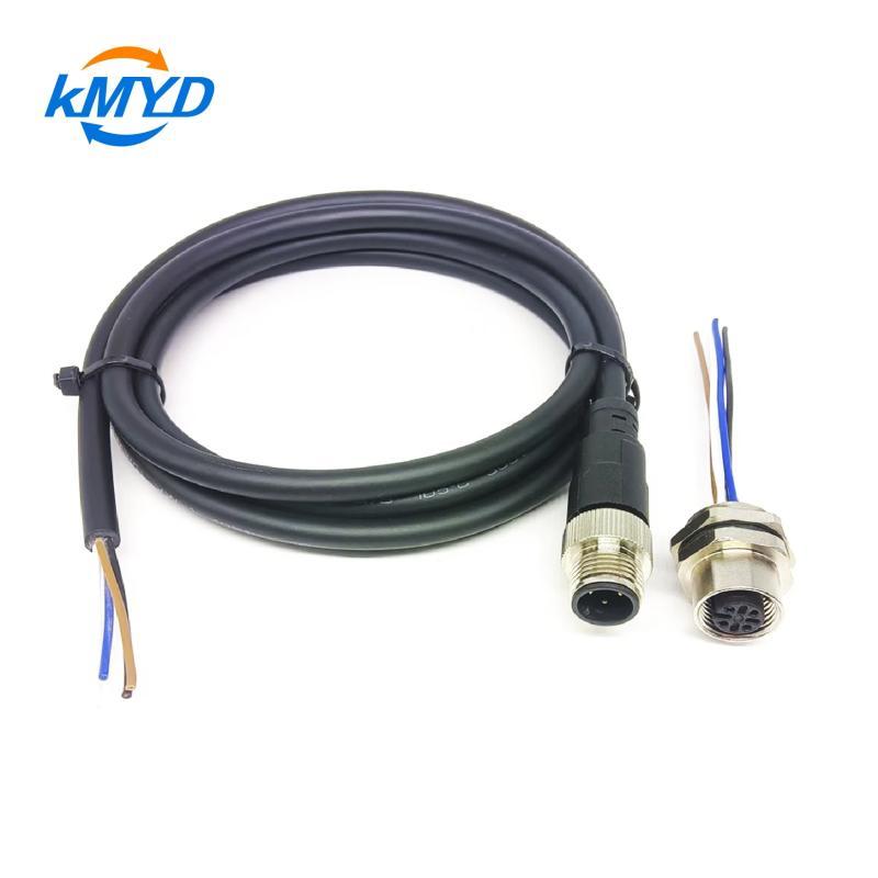
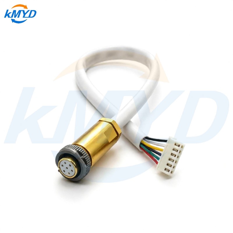
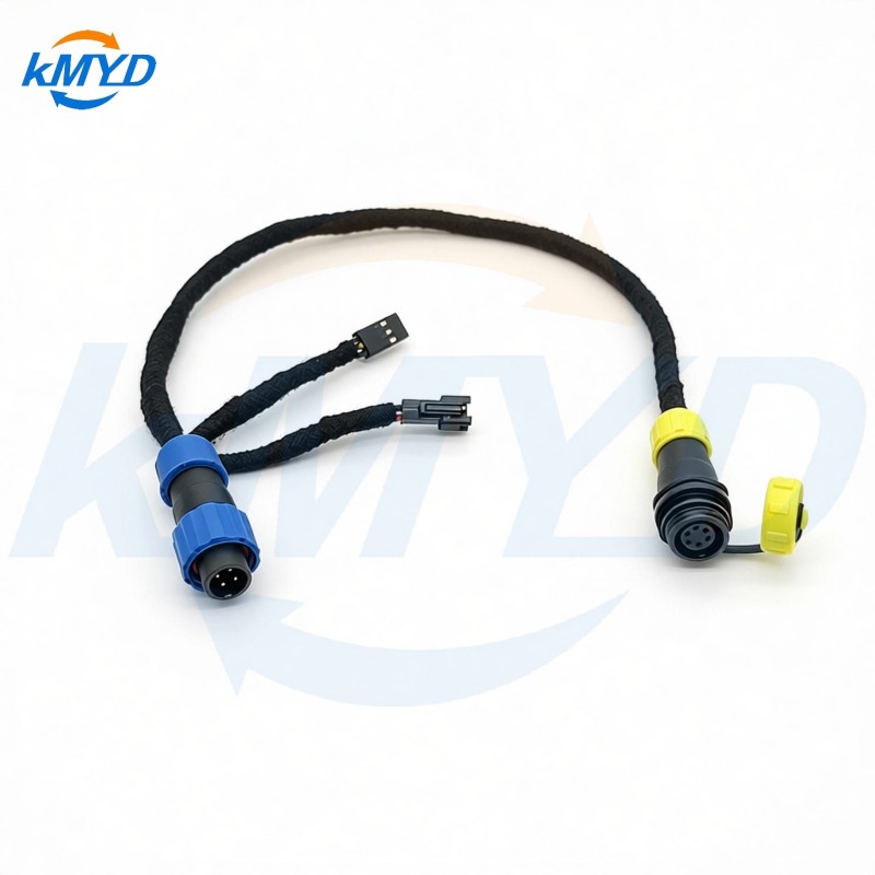
KMYD's custom cable assembly listing includes configurable wiring. That makes the ordered circuit, including any internal components, the starting point for the test scope. A generic product-table withstand figure cannot select a procedure for every configured assembly.
A current alarm needs interpretation
Cirris explains that a high-voltage current error can involve leakage, dielectric failure or capacitance that the test setup has not accommodated. A cable's conductors and insulation form capacitance, so current associated with changing the applied voltage must be considered by the specified procedure and instrument.
That distinction matters when reviewing an unexpected failure. An event during voltage application and a persistent leakage measurement after the defined settling interval provide different clues. Neither should be relabeled by guesswork. Keep the test stage, instrument message and relevant trace or measurement so the responsible specialist can examine the cause.
Contamination, damaged insulation, unintended exposed metal and fixture conditions are possible investigation paths, not conclusions supplied by one alarm. Check the documented setup and specimen condition before deciding whether the cable, fixture or program requires correction. Raising a limit simply to obtain a pass would change the question being asked.
Replace an ambiguous test line with two clear definitions
| Item to define | Insulation resistance | Dielectric withstand |
|---|---|---|
| Main reported quantity | Measured resistance and its minimum requirement | Specified stress and the applicable current/event decision |
| Electrical conditions | DC measurement voltage and defined reading conditions | Selected AC or DC method, voltage application profile and duration |
| Physical scope | Named isolated circuits and accessible test points | Named stress boundary and the permitted specimen configuration |
| Acceptance reference | The requirement establishing the resistance limit | The requirement establishing withstand and failure criteria |
The values must come from the governing design, applicable requirement and selected test method. A supplier's available tester range is not a recommendation to use its highest setting. Likewise, a component's operating voltage does not, by itself, define the voltage and duration for a finished-cable withstand assessment.
Keep continuity outside these definitions. Confirming the intended conductive paths is useful, but it does not replace an insulation assessment. The reverse is also true: an insulation pass cannot establish that every required conductor reaches the correct destination.
Do not let a later pass erase an earlier failure
A repeated test can produce a different outcome, including where the first event altered a small defect. Preserve the original result and have the investigation determine the allowed retest or disposition. Repeatedly applying stress until the display turns green is not an acceptance method.
When comparing offers, request separate confirmation of the insulation-resistance and dielectric-withstand requirements that actually apply. A concise answer should identify the two electrical questions and their agreed boundaries. That is more useful than a single “hipot” stamp whose meaning changes between the buyer, supplier and test station.
Test concepts: Cirris CR manual, section 15.4 on high-voltage test concepts; Cirris explanation of high-voltage error categories. The manual notes that the CR itself does not perform high-voltage testing.




 Tel: +8619924482730
 Email: info@kmydconnector.com
 MP/WhatsApp: +8619924482730
 Manufacturer Address:Baoan District, Shenzhen City, Guangdong Province,China