

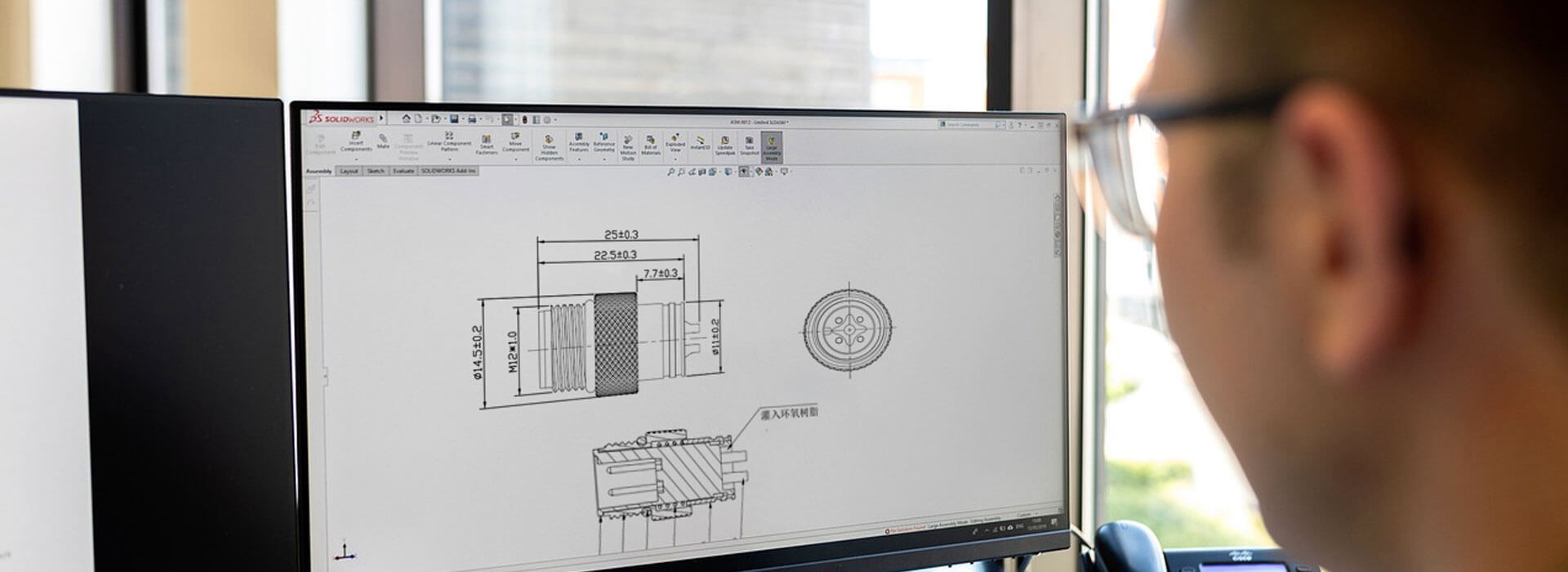
The allowable current of custom cable assemblies must satisfy every part of the current path under the intended operating conditions. A connector's headline rating alone cannot establish that limit. The cable conductors, contacts, terminations and any internal joins need compatible limits, while ambient heat and simultaneous circuit loading affect the assessment. Ask for an assembly-specific current statement tied to the actual construction and installation, rather than selecting the largest number on a product page.
Follow the current through the whole assembly
Start at one equipment terminal and follow the outgoing path through its mating contact, termination and conductor. Then trace the return path. If the assembly changes connector type, conductor size or termination method along that route, each change deserves attention. A generous contact rating at one end cannot compensate for an unsuitable component at the other.
A useful review separates the circuit demand from the capacity evidence. The designer states what must flow, in which circuits and for how long. The assembly supplier identifies the offered construction and the documented conditions under which it can carry that demand. Put an unresolved limit on the review list instead of silently borrowing a value from a similar-looking connector.
| Part of the path | Evidence to request | Condition that can change the answer |
|---|---|---|
| Mating contact pair | Ratings or derating data for the identified combination | Ambient temperature and simultaneously loaded contacts |
| Cable conductor | Selected cable specification and applicable installation basis | Loaded cores, grouping and heat dissipation |
| Wire termination | Compatibility of the contact, conductor and joining process | A conductor or termination substitution |
| Internal connection | Construction and limits of any splice or shared connection | Combined current from the circuits it serves |
| Equipment interface | The device terminal or port requirements | A lower equipment limit at either end |
The lowest applicable limit constrains the design, but comparing catalog numbers without their conditions is not enough to identify it. A value measured with a particular wire and loading arrangement is not automatically valid for a different assembled harness.
Describe the load as a pattern, not one number
A request that lists only total equipment current can hide how that current is distributed. Identify the normal current in each circuit, which circuits operate together, and any starting or intermittent demand that differs from continuous operation. Distinguish a brief event from a load that persists long enough to establish a different thermal condition.
Where several loads share a supply or return segment, assess that segment for the current it actually carries. Do not assign each branch's individual demand to a shared conductor without considering their simultaneous operation. Conversely, a circuit reserved for a future option should not be treated as permanently unloaded if the approved equipment configuration can use it later.
Record the permitted operating combinations. If a proposed limit depends on loads never running together, that is an equipment constraint to document and maintain. It should not exist only as an assumption in a supplier's calculation. Treat changes to the loading pattern as a reason to revisit the current assessment.
A cool room does not describe a warm enclosure
Phoenix Contact's connector test guidance explains derating in relation to ambient temperature and neighboring contacts. Its test arrangements illustrate why a current figure needs a stated loading basis. The curves in that guidance belong to the components being discussed; they cannot be applied as KMYD ratings or converted into a universal percentage reduction.
For the cable, LAPP identifies influences including the number of loaded cores, cable grouping, insulation and ambient temperature. This is why the same nominal conductor cross-section does not settle every installation. A tightly grouped route and an isolated lead may present different heat-dissipation conditions.
Describe the local environment around the assembly, including the enclosure, nearby heat sources and the intended cable grouping. Identify whether excess cable will remain coiled. Ask the responsible engineer and supplier which conditions their assessment assumes, and what changes would require another review. The relevant ambient condition is where the assembly operates, not simply the temperature outside the machine.
Request the proposed temperature limits for both the cable and connector materials. A claim that one material tolerates a higher temperature does not by itself approve the assembled connection at that temperature; the other components and their operating limits still matter.

Keep temperature, voltage drop and continuity separate
Electrical resistance produces both voltage drop and heating when current flows. These lead to different acceptance questions. A cable can stay within its thermal limits yet lose more voltage than the receiving device allows. A conductor choice that improves voltage drop may also require a different contact termination or cable entry, so changes should be reviewed as an assembly.
A continuity result establishes neither of those operating limits. It can confirm an expected conductive path under its test conditions while leaving performance at the intended load unresolved. Request a separate assessment of the permitted supply drop and thermal behavior where the application requires them. Do not turn a basic continuity record into a current qualification certificate.
Ask for a current statement that can survive a reorder
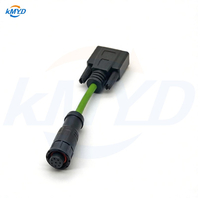
KMYD's M16-to-DB9 assembly page asks buyers to provide wire gauge and electrical load. Its custom cable offering also allows cable configuration to be discussed. Use those inquiries to obtain the exact proposed build and a coherent electrical specification; broad series figures do not resolve an individual assembly.
Record the approved continuous load, any separately assessed intermittent demand, loaded-circuit pattern, ambient conditions and installation assumptions alongside the assembly revision. Identify the document or verification record supporting that statement.
Before accepting a replacement cable, compare the proposed conductor, contacts and termination construction with that record. If an item changes, ask whether the current statement still applies. This gives procurement a specific electrical requirement to preserve even when two finished cables look identical.
Technical context: Phoenix Contact connector derating guidance; LAPP cable current-rating factors. Their product values are not ratings for KMYD assemblies.



 Tel: +8619924482730
 Email: info@kmydconnector.com
 MP/WhatsApp: +8619924482730
 Manufacturer Address:Baoan District, Shenzhen City, Guangdong Province,China