

M16 connectors and DB9 connectors can both fit their equipment while the cable between them carries the wrong signals. Fit establishes only part of compatibility. The equipment's electrical interface, contact assignments and required signal relationships must also agree. A custom adapter should therefore be released against the two equipment documents and an approved connection schedule. Neither the round connector nor the nine-position D-sub shape supplies that schedule on its own.
An adapter changes the connection; what else changes?
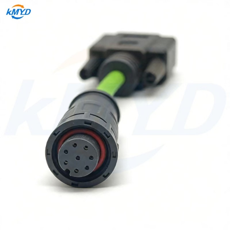
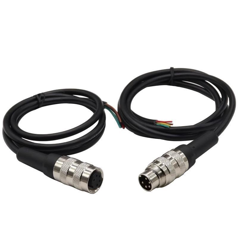
KMYD offers an M16 eight-contact female to DB9 female cable assembly. The product description includes customizable wiring and asks buyers for diagrams at both ends. That makes it a relevant starting point for adapting the physical interfaces. The listing does not give a universal contact-to-contact signal map for every device that accepts those connectors.
Begin by distinguishing a passive cable from a converter containing electronics. If the proposed item is a passive assembly, ask it to implement the specified conductive paths; do not assume it translates one electrical interface or protocol into another. If conversion is required, that becomes a separate system-design requirement that must be resolved before selecting the cable.
This distinction matters even when an older adapter “used to work.” The connected equipment may have changed model, port configuration or revision. Preserve the old adapter's identity and observed connections as evidence, then check them against the current equipment rather than treating its shape as proof of compatibility.
“DB9” is not a complete signal specification
The DB9 name describes a familiar connector arrangement; it does not uniquely identify the function assigned to each position. NI's own serial-adapter documentation shows different signal descriptions for RS-232 and RS-485 against the same DB9 contact numbers. That is equipment documentation for NI interfaces, not a ready-made wiring map for another manufacturer's device.
Obtain the manual for the actual port and note its electrical interface, signal names and operating mode. For a configurable device, record the selected mode as part of the installation information. Two equipment manuals can both mention a serial connection while requiring different wiring relationships or settings.
Do not solve an unexplained failure by swapping conductors until communication starts. An undocumented contact could carry power, a reference or a control function. Refer the disagreement to the equipment designer and use the specified service procedure. A successful exchange of a few messages would still leave the unsupported wiring decision unresolved.
Compare signal roles before contact numbers
Place the equipment descriptions side by side and identify the role of each required circuit. Which signal leaves one device? Which input is intended to receive it? Does the interface use a signal reference, a differential pair, separate control lines or intentionally unused positions? Resolve those relationships before assigning cable conductors.
Matching words can be misleading when they are written from different viewpoints. A port label might describe what the local device transmits, while a cable table describes a destination at the far end. Retain the device names in the schedule so “transmit” is attached to a particular endpoint. Where the manuals use inconsistent names, record their original labels and the engineer's interpretation.
An eight-to-nine connection is not an instruction to invent a ninth circuit. Show how the required equipment circuits are accommodated. Mark unused contacts explicitly, and document any common connection only when the equipment design requires it.
The assembly supplier can then turn the agreed signal relationships into a contact schedule. Both connector views and exact component identities should accompany that schedule. This article deliberately supplies no numbered pinout: a convenient generic map could be precisely the cause of the mismatch being investigated.
Use the evidence to place the fault
If the measured assembly differs from its approved schedule, investigate the cable build, identification or inspection reference. If it matches the schedule but the devices still do not communicate, return to the equipment requirements and operating configuration. Rebuilding an identical cable will not correct a schedule that describes the wrong interface.
Keep communication testing separate from wiring verification. A connection measurement answers whether selected electrical paths meet a defined requirement. An equipment test asks whether the assembled system performs the specified function. Either can pass while the other remains incomplete, especially when the equipment test exercises only a subset of the intended functions.
For a fault report, record the equipment references, port settings, assembly identifier and drawing revision, then describe the observed symptom without declaring the cable defective prematurely. “No response from port X with configuration Y” gives the reviewer more to work with than “DB9 cable incompatible.” It also makes a later corrective change easier to evaluate.
Close the undocumented interface first
Before asking for another sample, identify the missing decision. It may be a port mode, the role of a control line, an unused contact or the need for an active converter. Assign that question to the party responsible for the equipment, then revise the connection schedule after it is resolved.
For KMYD's M16-to-DB9 assembly, submit the two equipment interface pages with the proposed schedule and request an explicit statement of what the cable will connect. That gives mechanical adaptation a defined electrical purpose and prevents the next order from repeating the same uncertainty.
Equipment-specific example: NI serial connector assignments. These assignments belong to the described NI interfaces and must not be copied to an unspecified M16 adapter.


 Tel: +8619924482730
 Email: info@kmydconnector.com
 MP/WhatsApp: +8619924482730
 Manufacturer Address:Baoan District, Shenzhen City, Guangdong Province,China