


Approve an M12 cable assembly to RJ45 against an equipment-specific connection map, not a picture found by searching the connector names. The map needs to identify both interfaces, their numbered contacts, the circuit carried between them and any deliberately unused positions. It must also match the intended data service. A cable can reproduce a drawing perfectly while that drawing belongs to a different connector coding, port or equipment revision.
Follow the documents
Document 1: identify the ports being joined
Start with the equipment manuals, recording the device and port reference at each end. Some machines have several connectors that look alike but serve different purposes. “The RJ45 on the controller” is less useful than the actual port designation and the manual revision defining it. Include whether the connection is an Ethernet interface or another equipment-specific use of the connector.
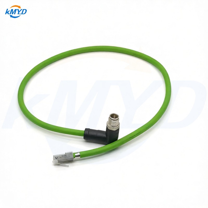
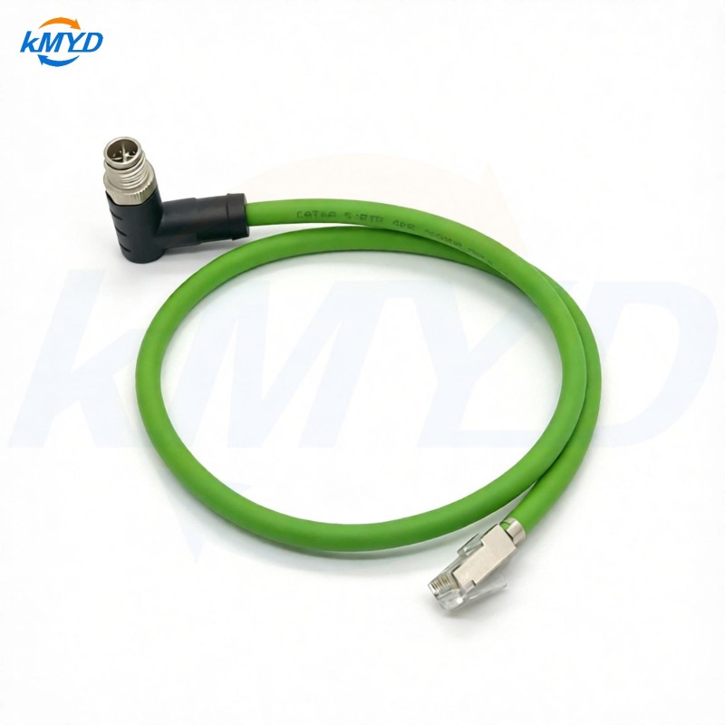
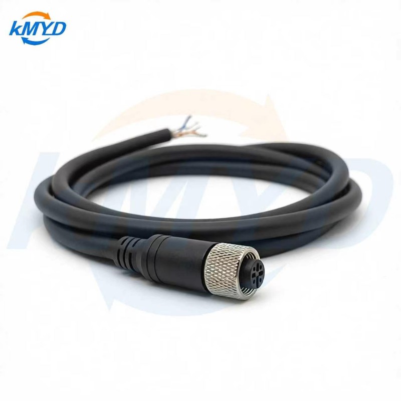
For the M12 side, obtain the specified coding, contact arrangement and mating component. KMYD lists an eight-contact X-coded M12 to RJ45 assembly. That is a verified product route for discussing this arrangement; it is not a reason to apply a four-contact D-coded diagram to it.
A public manufacturer example illustrates the distinction. Phoenix Contact's separately identified M12-to-RJ45 product 1561797 uses a four-position D-coded M12 interface and publishes its own connection documentation. Its drawing describes that product. It does not define the wiring of KMYD's X-coded assembly or the port on your machine.
Document 2: make every connection accountable
The assembly map translates the equipment requirement into a buildable record. Give each cable end a stable designation and list where each required contact goes. Include signal or pair identity where the equipment documentation provides it. Show unused contacts explicitly; an empty cell otherwise leaves the reviewer guessing whether a connection was forgotten.
A useful map is more than a row of colors. Cable constructions can use different color conventions, while the destination contact remains the same. Colors may help an assembler follow the drawing, but they should be checked against the selected cable's documentation. The electrical requirement is the defined connection, not a familiar color sequence.
| Field | What the reviewer resolves |
|---|---|
| Equipment reference | Which device and port require this connection? |
| M12 contact | Which numbered position on which identified connector? |
| Circuit or pair | Which equipment-defined signal group must be preserved? |
| RJ45 contact | Which numbered destination in the stated connector view? |
| Exception | Unused position, special termination or unresolved requirement? |
This is a documentation checklist, not a wiring diagram. The actual contact numbers must come from approved equipment and connector records. Attach end-view drawings that state what the reader is looking at; a contact table without its reference view can still be misinterpreted during assembly or inspection.
When two source documents disagree, preserve both references and raise the conflict with the equipment owner. Do not silently reconcile them using a generic internet pinout. In particular, an older working cable can be useful evidence, but its wiring needs to be identified and justified before becoming the master for a replacement build.
Document 3: state what the installed link must do
The connection map addresses conductor destinations. The system specification addresses the required communication service. Record the interface and operating requirement from the equipment documentation, together with any applicable cable construction or link-verification requirement. Avoid assigning a cable category or transmission rate from connector appearance alone.
A simple wire check may find an open circuit or an incorrect destination, yet leave other data-cable requirements unevaluated. Pair organization and the assembled connection need the evidence selected for the application. If a supplier proposes a test report, ask which characteristic it measures and which configuration was tested. Do not accept a generic report as confirmation of an unidentified custom build.
Connector adaptation does not guarantee protocol conversion. A passive cable joins specified electrical paths. If the equipment requires incompatible interfaces, a different connector at the far end does not by itself make those interfaces communicate.
Keep screen termination and mechanical routing requirements on their own drawing details. They can affect the final build, but adding a long shield note or a routing sketch should not hide an unresolved signal assignment in the connection table.
Put the three documents through one review
Before releasing the sample, have the equipment owner confirm the port requirements, the cable supplier acknowledge the assembly map and the responsible engineer define the necessary verification. Record unresolved items beside the relevant row instead of burying them in an email chain. A revised map should trigger a check of the sample and test reference, not just a new file name.
The final approval question is precise: does this identified assembly implement the required connections between these two identified ports, with suitable evidence for the requested service? Send that question with the map when discussing KMYD's M12-to-RJ45 offering. It invites a verifiable answer without asking a product photograph to serve as an electrical specification.
Interface-specific reference: Phoenix Contact product 1561797. Its D-coded documentation is not a KMYD pin assignment. Testing background: Fluke Networks on different cable-test scopes.



 Tel: +8619924482730
 Email: info@kmydconnector.com
 MP/WhatsApp: +8619924482730
 Manufacturer Address:Baoan District, Shenzhen City, Guangdong Province,China