

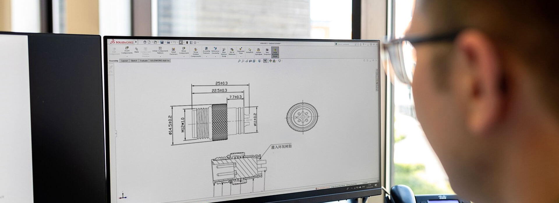
An M16 cable assembly needs a defined mechanical path for pulling, bending and twisting forces. The specified cable retention and surrounding supports should handle those loads without relying on the electrical terminations. Check the jacket grip, connector transition and machine routing together: a strong-looking housing does not show what happens to the conductors inside it. The exact retention parts, cable compatibility and assembly method must come from the selected connector and cable documentation.
Trace a cable pull toward the contacts
Picture a cable hanging from a vertical connection or being moved during service. Ask what restrains that movement before it reaches the individual conductors. Depending on the assembly, retention may involve a specified clamp, a molded transition or another documented construction. Identify the actual arrangement rather than describing every rear nut or boot as strain relief.
A soldered or crimped electrical connection is not a substitute for the assembly's specified cable retention. Nor does a visible gland prove that a particular cable will be held correctly. The retention design must suit the cable construction, and it must be assembled as intended. Adding more material around the wires does not establish that a load path has been created.
Keep three functions separate during the review: electrical termination, protection against ingress and mechanical restraint. A component may contribute to more than one function, but success in one check does not automatically demonstrate the others. For example, a correctly mapped circuit can still have an unsupported cable exit.
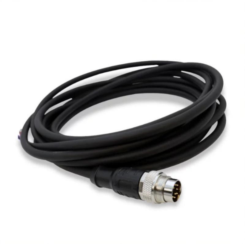
Pulling, bending and twisting need different questions
Axial pull
What limits cable movement along its length? Identify the retained jacket area and any equipment support that carries hanging cable weight.
Side bend
Where does the cable begin to curve? Check the permitted bend and the transition so the route does not force a sharp turn at the housing.
Torsion
Can installation or repeated movement twist the cable? A support that limits pulling may not provide the required control of twisting.
These questions concern the installed assembly, not just the connector supplied in a bag. A fixed instrument cable, a hinged-panel connection and a moving machine cable can impose different combinations of load. State the actual motion and supports rather than selecting a construction from the M16 name alone.
Binder's published discussion of an M16 molded construction treats force distribution and resistance to twisting as separate design concerns. It illustrates why transition geometry matters. It does not demonstrate that another manufacturer's molding has the same construction, mechanical capability or service life.
Make the cable and retention parts one controlled combination
For an assembled connector, obtain the permitted cable range, cable preparation requirements and identification of the retention components. Confirm whether the restraint is intended to act on the intact outer jacket, and where that jacket must sit. Those details cannot be recovered reliably from a photograph of the closed housing.
Do not make an undersized cable “fit” by improvising packing, tape or an extra sleeve unless the manufacturer has specifically approved that construction. Likewise, tightening an entry component further is not a documented solution to cable movement. Ask for the correct parts and the assembly instruction instead of inventing a tightening value.
For a molded cable assembly, request the construction reference and the mechanical conditions covered by its verification. The visible boot can show where the cable leaves the housing, but it cannot reveal the internal retention arrangement. A change of cable jacket, diameter or molding construction should prompt confirmation that the reviewed combination still applies.
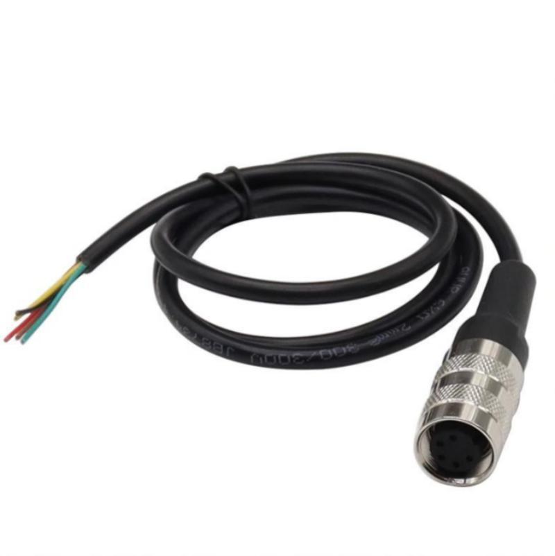
Let the machine support the route without damaging the cable
Include the first support point in the equipment layout and review the cable between it and the connector. A clamp that leaves the span taut can transfer movement directly to the housing. Excess unsupported cable can catch on adjacent equipment. The arrangement needs enough freedom for the intended service and motion while respecting the cable's documented bend requirements.
Choose supports appropriate to the jacket and environment. A tight tie mark or flattened jacket is a reason to review the support method, not evidence of secure retention. Where the cable repeatedly moves, establish the permitted moving region and keep fixed restraints consistent with the cable system's instructions.
Also review assembly order. The cable should not be left suspended from newly terminated wires while a housing or panel is installed. Plan a temporary support or an assembly fixture where needed, and make sure it does not obstruct the final retention parts.
Agree the mechanical evidence before approving the sample
Ask for an inspection of the specified retention construction and a mechanical verification appropriate to the intended use. A useful record identifies the connector, cable, assembly revision, loading direction, method, acceptance condition and any electrical checks performed before and after it. The responsible engineering parties should set those conditions; an arbitrary workshop pull is not a substitute for an agreed method.
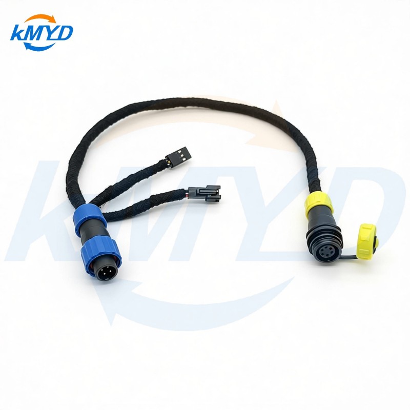
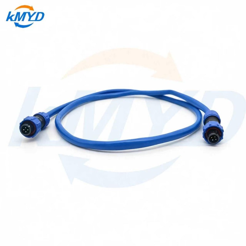
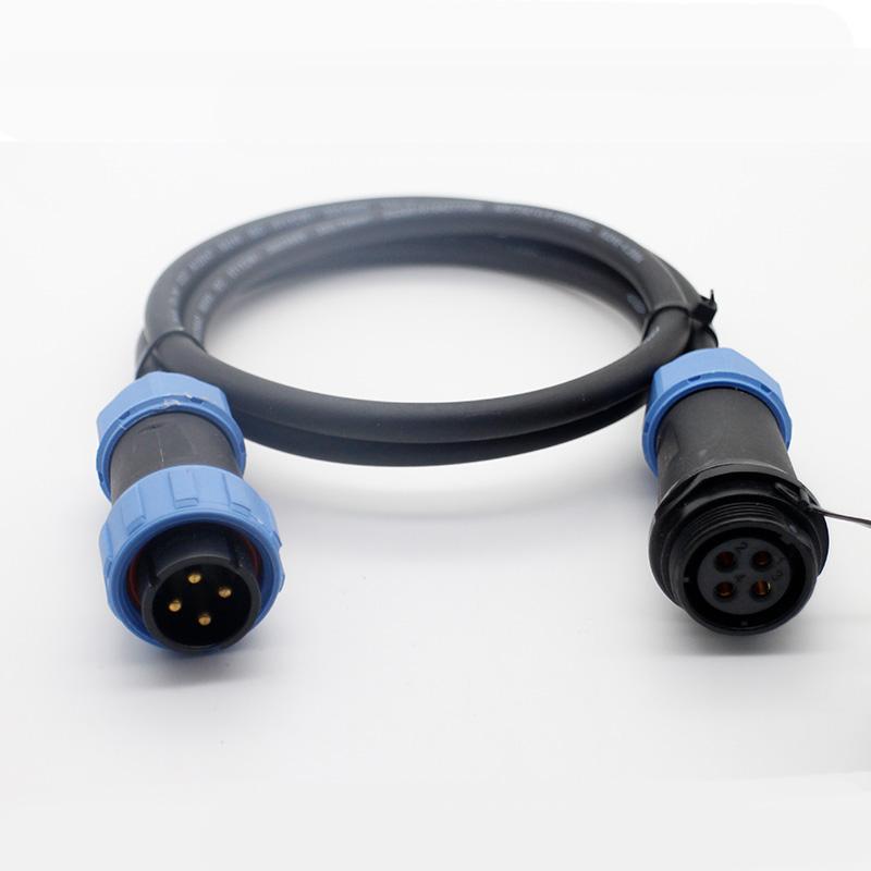
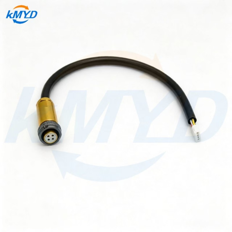
KMYD's M16 connector and cable configurations provide a starting point for that discussion. Send the installed cable route and the anticipated handling or motion along with the electrical drawing. Resolve who supplies the connector's retention and who supplies the equipment supports before ordering production quantities. That division of responsibility is what turns “add strain relief” into an assembly requirement that can actually be inspected.
Technical context: Binder's M16 cable-transition design discussion. The cited geometry and product performance are specific to Binder's construction.

 Tel: +8619924482730
 Email: info@kmydconnector.com
 MP/WhatsApp: +8619924482730
 Manufacturer Address:Baoan District, Shenzhen City, Guangdong Province,China