

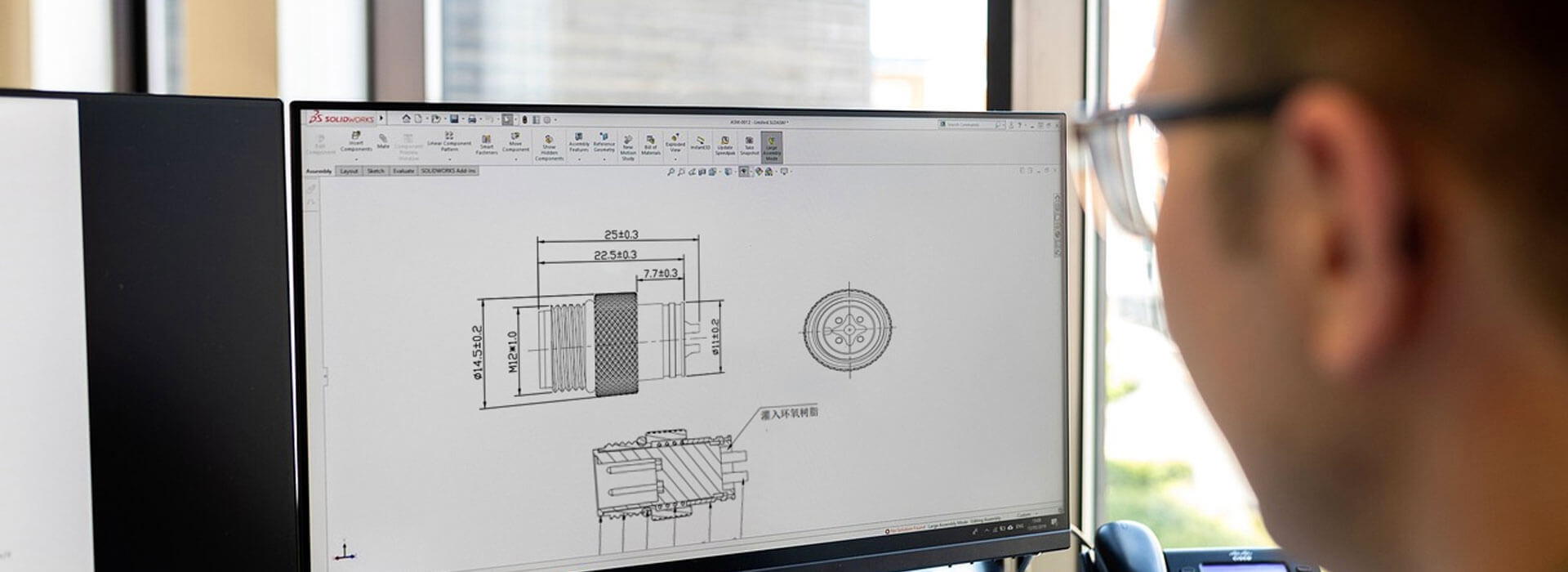
For custom cable assemblies, specify length with visible start and end references, a defined measurement condition and an agreed tolerance. A nominal dimension on its own is incomplete: two people may include different parts of the connectors, measure different branch paths or straighten the cable differently. Put the dimension on an assembly drawing before approving the order, then use that same definition when checking the sample and subsequent deliveries.
Start by drawing the dimension arrows
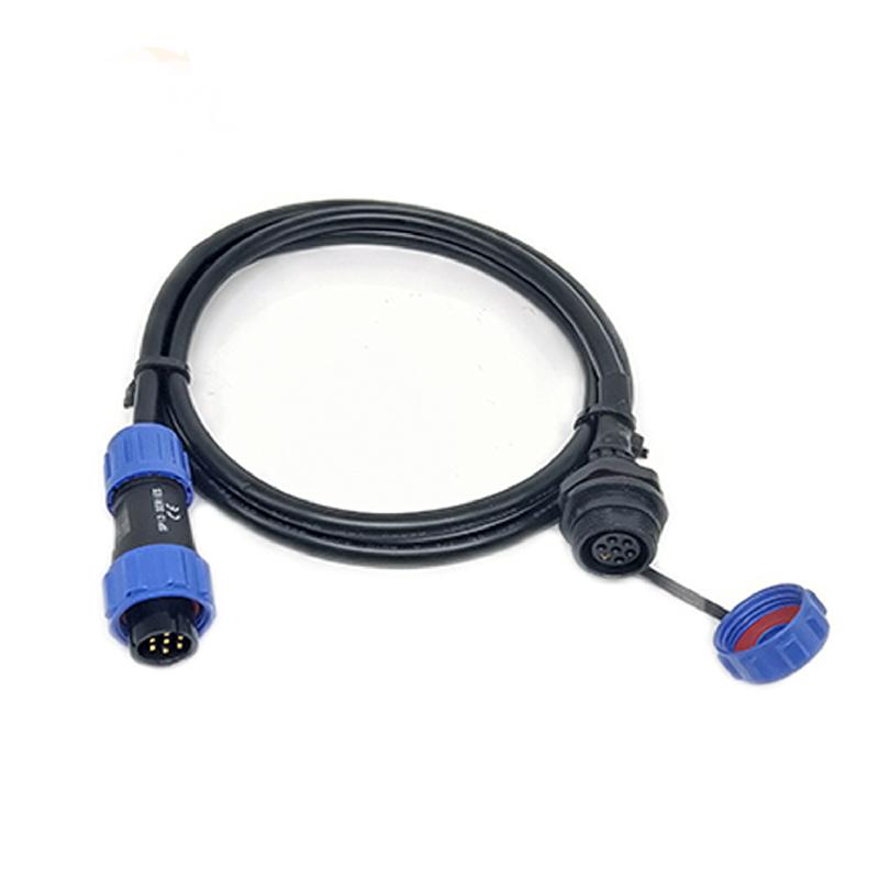
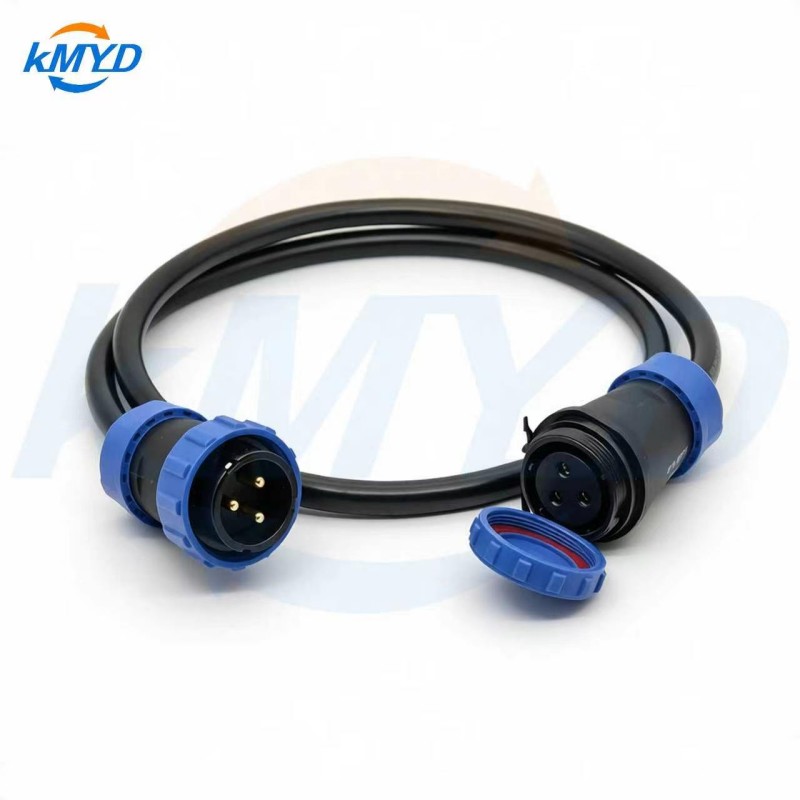
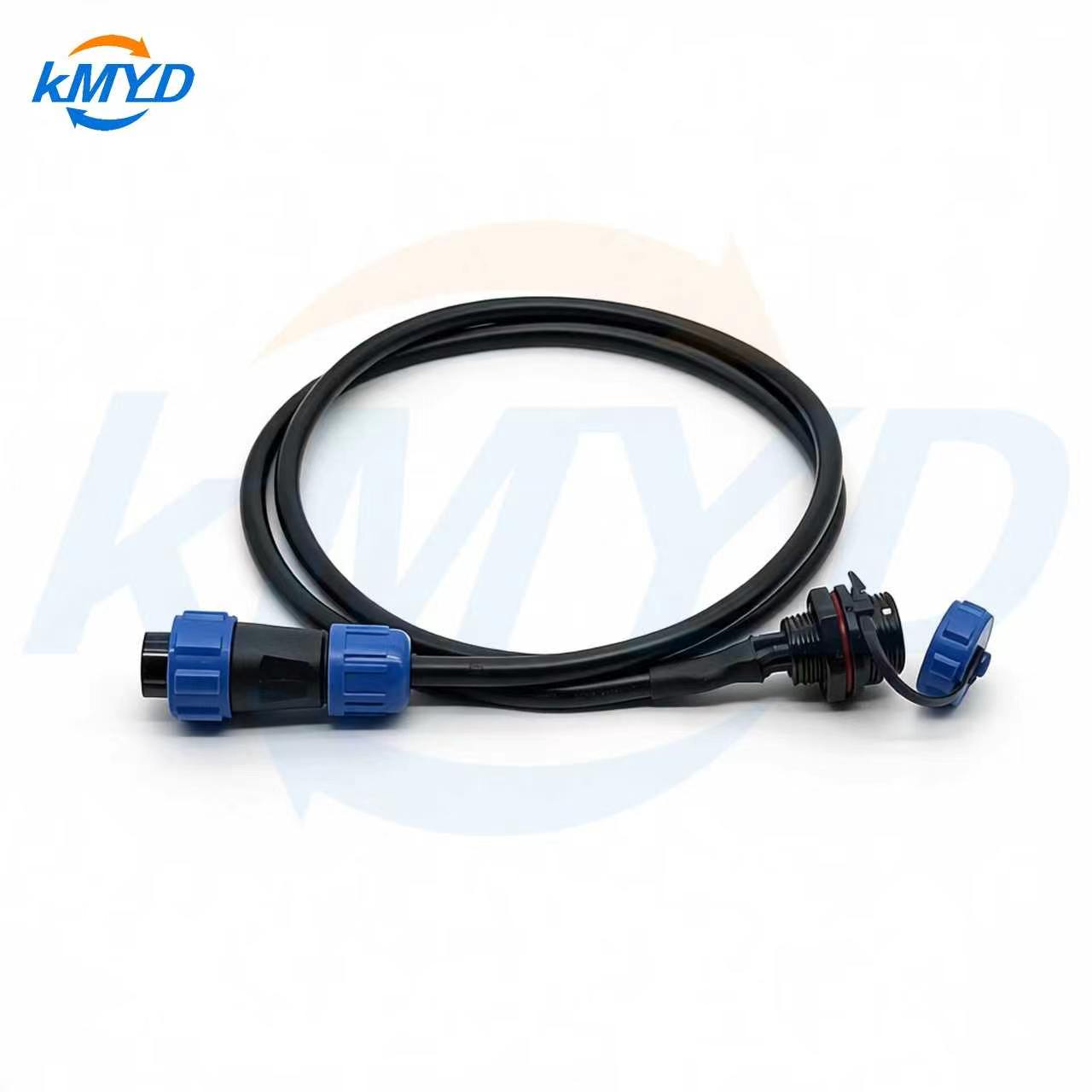
Take a simple cable with a connector at each end. “Overall length” might be understood as the distance between the front faces, the back faces or the extreme ends of the assembly. These references are not interchangeable. Mark the two chosen surfaces on the drawing and make clear whether connector bodies and strain-relief sections are included.
Choose references that the supplier can identify consistently on a completed assembly. If a coupling nut can move, clarify its position during measurement or use another agreed fixed feature. If an overmold hides the original connector rear face, a dimension to that hidden face needs a practical inspection method.
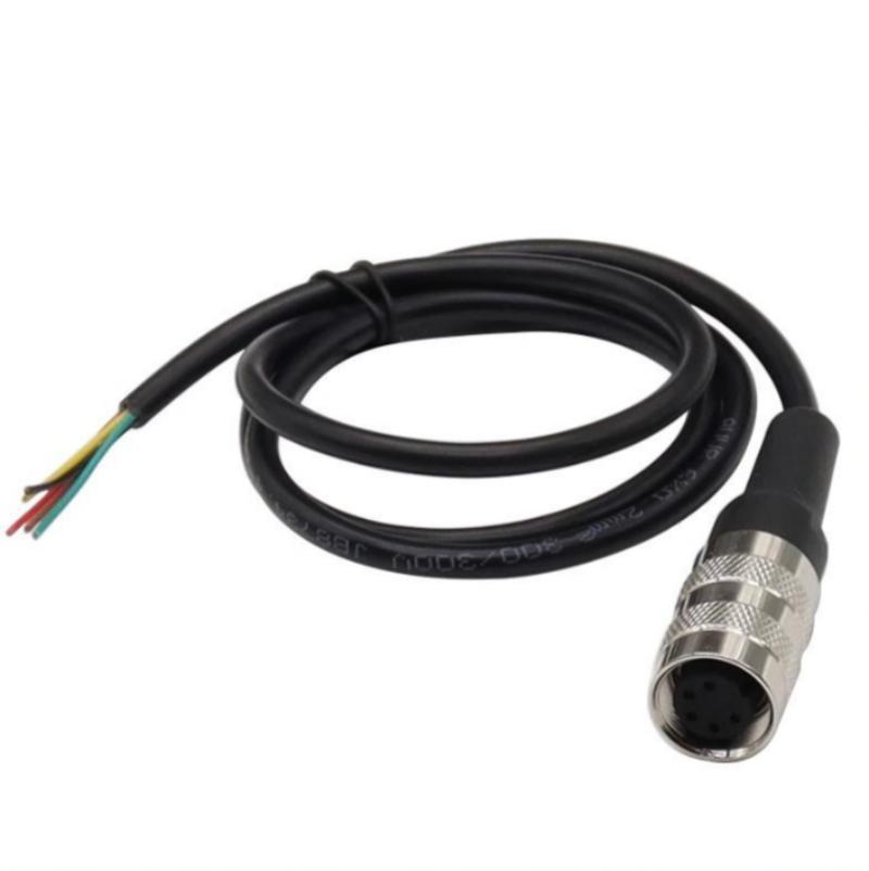
For a lead with one open end, distinguish the jacket end, conductor ends and any fitted terminals. Define conductor breakout and stripping dimensions separately from the main assembly length. Otherwise, a supplier can satisfy the apparent overall dimension while leaving too little conductor length for the terminal block.
Keep the installation route and inspection dimension connected
The route through a machine establishes how much usable reach you need. The assembly drawing establishes what the supplier makes and measures. Record both so that an approved drawing can be checked against the installation instead of treating a straight-line distance between ports as the finished cable requirement.
Mark routing clips, enclosure entries and the point where the cable starts to bend away from a connector. Account for access needed during installation and servicing. If slack is required, identify where it can be stored; extra cable near a moving part may be as troublesome as insufficient reach.
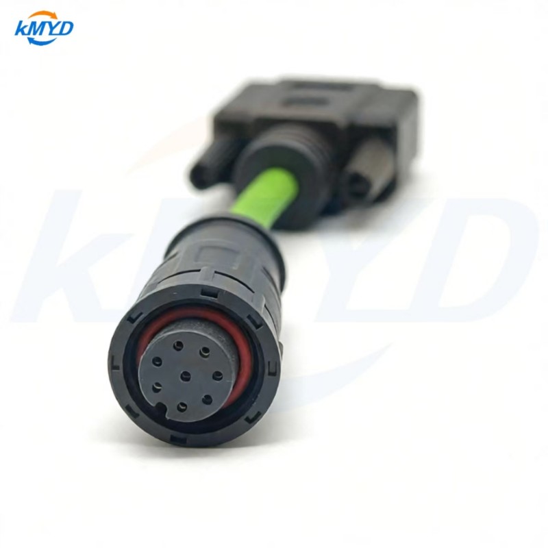
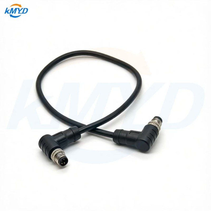
A right-angle connector deserves its own view. Define the end references and the exit orientation relative to the mating feature. Rotating the connector or changing its body can alter the usable reach even when the specified cable length stays the same. Keep minimum bend requirements tied to the selected cable documentation.
Agree how the finished assembly will be laid out for measurement. State whether it is relaxed on a surface or held in a fixture, and identify any positioning condition that affects the result. Do not leave the buyer and supplier to apply different pulling forces or different bends while deciding whether the same sample passes.
Choose the acceptable window from the equipment layout
Ask what happens at each end of the proposed tolerance: can the shortest acceptable assembly reach without loading a connection, and can the longest acceptable assembly fit its allocated route? Review the extremes before deciding that a tighter tolerance is necessary. The production tolerance is a design decision to agree, not a number to copy from an unrelated cable.
Some installations have a hard minimum reach but space for additional length. Others have little room for excess cable. Show the allowed upper and lower deviations explicitly, including when they are unequal. Ask the supplier to confirm that the requested window is achievable with the chosen connectors, cable and manufacturing process.
Molex's cable assembly design guide discusses reference surfaces and the manufacturing implications of tight dimensional tolerances. Its recommendations apply within the scope of that guide. They are useful context for a discussion, but they do not establish a default tolerance for a KMYD assembly.
For a harness, locate the breakout as well as the ends
A branched harness can have correct endpoint lengths and still be difficult to install if the breakout is in the wrong place. Identify a common starting reference, the branch point and each destination. State whether each dimension follows the cable path or another defined measurement line.
Give repeated branches distinct labels. If two nearby devices use similar connectors, relate each branch label to both its endpoint and its length dimension. This lets the installer distinguish the branches without relying on the way the harness was coiled in its packaging.
| Drawing element | Question to resolve |
|---|---|
| Main length | Which fixed references bound the dimension, and what is included? |
| Branch location | Where does the breakout sit relative to the common reference? |
| Branch length | Which route and endpoint define each named branch? |
| Open leads | Are jacket removal, conductor reach and terminal preparation shown separately? |
| Acceptance | Are units, upper and lower limits, and measurement conditions unambiguous? |
KMYD's custom cable solutions process includes drawing-based length, branch and end-treatment requirements. Submit the route sketch with those fields rather than sending only a single nominal length.
Make the first measurement reproducible
When the sample arrives, record its drawing revision and check the same surfaces under the agreed measurement conditions. Note the result against the stated limits, then confirm that the assembly follows the intended route. These checks answer different questions: one assesses drawing conformance, while the other checks whether the design suits the equipment.
If the measurements disagree, first compare the references and setup. A photograph showing the measuring points can resolve an interpretation problem before either party changes the nominal dimension. If the installed route needs more cable, revise the design deliberately rather than treating every satisfactory-looking sample as a new reference.
For the next quotation or reorder, attach the approved length drawing and its revision. Mark changed endpoints, branch positions or connector bodies so the supplier can review their effect on the finished assembly. That gives a later delivery the same measurable target as the accepted sample.



 Tel: +8619924482730
 Email: info@kmydconnector.com
 MP/WhatsApp: +8619924482730
 Manufacturer Address:Baoan District, Shenzhen City, Guangdong Province,China