


A specification for M12 cable assembly shielding needs to show where the cable screen connects at each end and how that connection meets the equipment. The word “shielded” identifies a cable feature; it does not describe the complete installed path. Request the cable construction, connector termination arrangement and equipment-side requirements together. Agree what evidence will demonstrate the intended connections before treating a metal housing or a continuity result as proof of the finished assembly's electromagnetic performance.
Separate cable construction from the connection path
A quotation may name a shielded cable without explaining what happens to its screen inside either connector. Another offer may show a metal connector body while leaving the cable construction unspecified. Neither description is enough to compare the two assemblies.
Read the specification as three linked records: the cable's construction, the way its screen terminates inside the connector, and the interface to the connected equipment. Each record answers a different question. A change to one may require review of the others, even if the connector size and contact count remain unchanged.
KMYD's custom M12 cable offering includes shielded and unshielded cable options. That gives you an appropriate product route for discussing a screened assembly. It does not select the termination arrangement for your equipment, or provide a measured immunity result for an unspecified build.
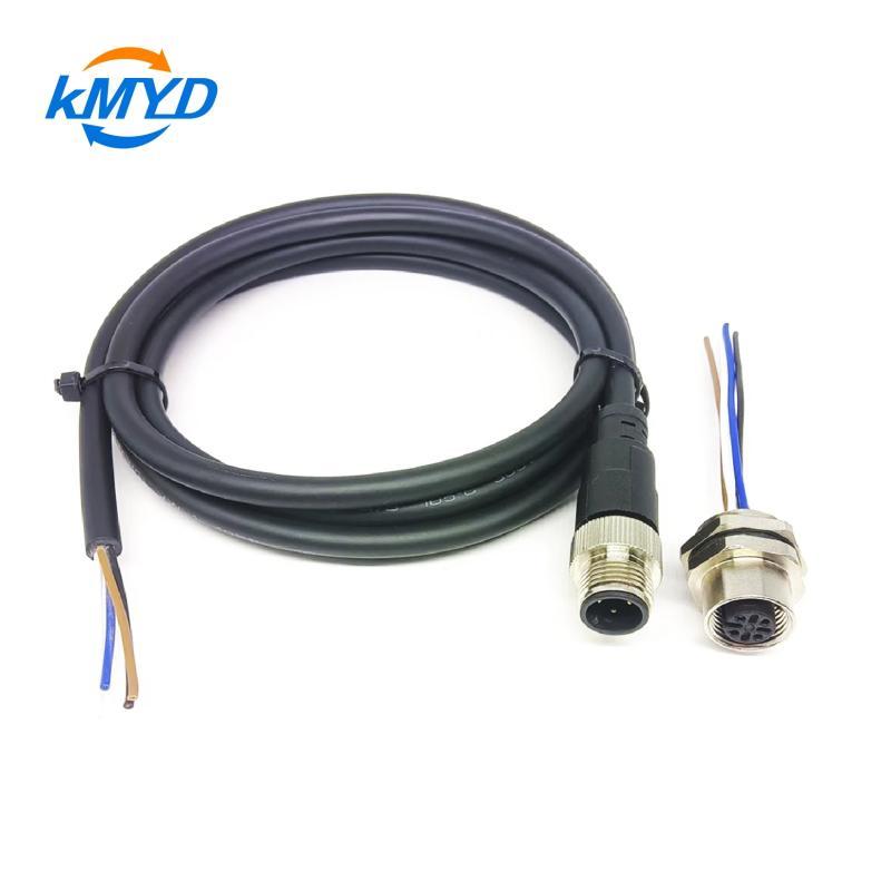
Trace the screen through both endpoints
Start at one equipment interface and follow the intended screen path to the other. Label the cable screen separately from signal conductors. Where the design uses a drain wire, name it and show its termination; do not leave its function implicit in a wire-color list.
Show whether the screen connects to a connector housing, a designated contact, an equipment terminal or another specified point. Include intentional isolation and any interface between the connector housing and enclosure. Avoid silently treating the cable screen, signal reference, chassis and protective earth as interchangeable labels.
The equipment manual determines the required arrangement. Beckhoff's documentation provides useful examples of why there is no universal M12 shielding map: its ER9320 connection page assigns the screen to the housing, while a separate PROFIBUS interface describes a screen contact with a capacitive connection to the device base. These examples belong to their identified interfaces and must not be copied onto another device's wiring drawing.
For a connector-to-open-end assembly, include the screen preparation at the open end. State what the installer receives and which termination is completed on site. That makes the boundary between the cable supplier's work and the panel builder's work visible.
Ask each document to answer one question
| Document | Useful detail | What it does not establish alone |
|---|---|---|
| Cable data sheet | Overall or individual screens, construction and the exact cable reference | How the screen is terminated inside the finished connector |
| Assembly drawing | Screen endpoints, connector references and any intentional isolation | Performance of the complete installed machine |
| Termination detail | The specified contact method and assembly requirements | That every supplied unit was assembled correctly |
| Inspection record | Identified sample or batch, checked points, method and acceptance criteria | Unmeasured behavior outside that check's scope |
When an offer uses a phrase such as “full shielding,” ask which parts of the connection it describes. Obtain the relevant drawing or construction detail. A label on the quotation should lead to something that can be reviewed; it should not replace that evidence.
Record the actual cable and connector part references rather than allowing a generic family name to stand for them. If the supplier proposes a substitute, compare the screen construction and termination method as well as the visible dimensions. Similar appearance is not a sufficient basis for accepting a change.
A continuity check answers a limited question
An electrical continuity check can help determine whether an intended conductive path is present between defined points. It needs a stated method, access points and acceptance limit. Agree those with the responsible engineer instead of inserting a universal resistance threshold into an otherwise incomplete specification.
Do not turn that result into an electromagnetic compatibility claim. The check does not, by itself, measure shielding effectiveness over a frequency range, establish data-channel performance or demonstrate the behavior of the installed equipment. Those are different questions requiring evidence appropriate to the application.
Intentional isolation also matters. A path that is meant to be isolated, or connected through a component, should not be assessed as though the drawing required a direct wire connection. The test record must refer to the specified circuit, not merely report that two exposed metal parts produce a reading.
Where electromagnetic testing is required, identify the responsible party, test configuration and acceptance requirement. Keep those requirements separate from routine assembly inspection so a buyer can see what has been measured and what still needs system-level verification.
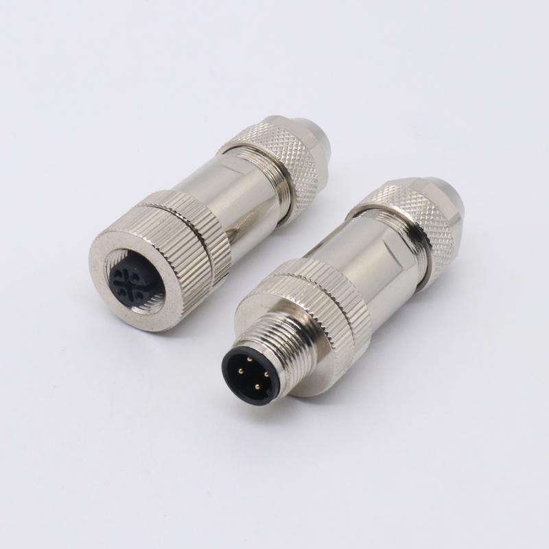
Carry the agreed arrangement into installation
Document any field termination or enclosure connection that the supplied cable cannot complete by itself. Installation instructions should identify the required hardware and connection points from the equipment design, including any specified preparation of mating surfaces. Do not ask an installer to infer the intended bond from a product photograph.
Use the selected component instructions for cable preparation and assembly. A metal-bodied connector is not automatically the same as a connector whose screen termination has been specified and verified. KMYD's M12 connector product page can help identify a proposed component; request its applicable termination details before accepting it for a screened build.
Before ordering, resolve one concrete question: can the supplier and equipment integrator trace the same screen path on the drawing? Keep that marked drawing, the agreed inspection scope and any required system evidence with the assembly revision. That gives a repeat order a defined connection arrangement instead of another request for an unspecified “shielded M12 cable.”
Interface-specific examples: Beckhoff ER9320 M12 housing connection and Beckhoff PROFIBUS screen connection. Consult the documents for your own equipment before defining the wiring.


 Tel: +8619924482730
 Email: info@kmydconnector.com
 MP/WhatsApp: +8619924482730
 Manufacturer Address:Baoan District, Shenzhen City, Guangdong Province,China