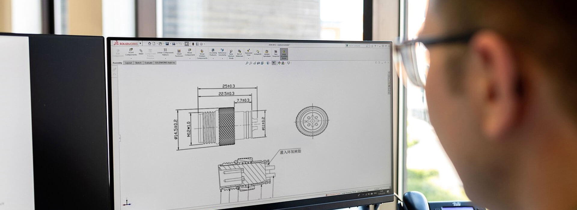
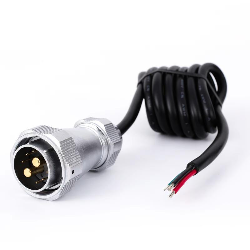
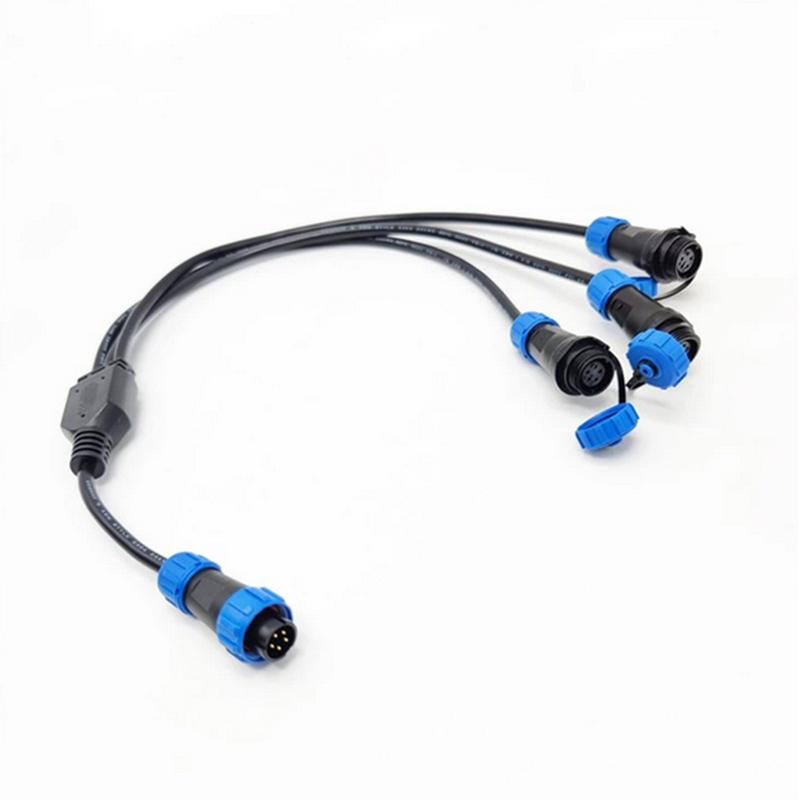
PCB-mounted M12 socket connectors are board-level circular Ethernet interfaces used to connect an industrial switch panel with its internal printed circuit board. Instead of using a separate internal cable harness, the connector is fixed to the enclosure panel while its rear contacts are soldered directly to the PCB. This structure gives the switch a compact, sealed, and mechanically stable front interface.
In industrial Ethernet switch design, this connector type is commonly used in rail transit, vehicle manufacturing, outdoor network nodes, factory automation, and other environments where vibration, dust, water spray, and repeated field maintenance must be considered. This article explains the technical role of PCB-mounted M12 sockets, the difference between D-coded and X-coded Ethernet versions, and the key design points for PCB layout, soldering, grounding, and selection.
Definition and Design Scope
A PCB-mounted M12 socket is a through-panel M12 receptacle with rear contacts designed for direct soldering to a printed circuit board. It may use through-hole pins, SMT leads, or a mixed structure with support posts. On the equipment side, the connector presents a standard M12 circular interface for the field cable. On the internal side, it becomes part of the PCB signal path.
The design purpose is broader than signal transmission. The connector must provide mechanical fastening, environmental sealing, electrical continuity, and shielding support. When a field cable is inserted or tightened, the flange and panel should carry most of the mechanical force. The PCB solder joints should mainly provide electrical connection, not structural support.
| Term | Meaning | Buyer Relevance |
|---|
| PCB-mounted M12 socket | M12 receptacle fixed to the panel and soldered to the PCB. | Reduces wiring and saves enclosure space. |
| D-coded M12 | Four-contact Ethernet M12 interface. | Commonly used for 100 Mbps switch ports. |
| X-coded M12 | Eight-contact Ethernet M12 interface. | Used for Gigabit or high-bandwidth ports. |
| Flange sealing | Sealing between connector flange and panel. | Supports IP67 protection when correctly assembled. |
Definition note: IP protection, Ethernet speed, and long-term reliability are not determined by the connector alone. They also depend on mating cable quality, panel machining, gasket compression, PCB layout, soldering quality, and final assembly inspection.
Structure and Interface Logic
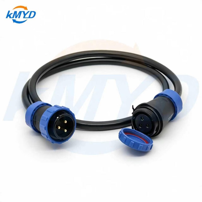
A typical PCB-mounted M12 socket includes a threaded front interface, a connector body, a mounting flange, sealing ring, positioning features, shield contacts, and rear PCB terminals. The connector is inserted through the equipment panel and locked by screws or a flange structure. The rear pins then align with the PCB footprint for soldering.
This creates a "panel-connector-PCB" structure. The panel defines the external port position. The connector provides mating geometry, sealing, shielding, and signal transition. The PCB provides differential-pair routing, Ethernet magnetics connection, grounding, and switching circuitry. If this structure is designed correctly, external cable stress is transferred to the panel instead of directly loading the solder joints.
The flange is therefore not a secondary detail. It controls insertion force, mating torque, vibration resistance, and panel sealing. If the flange screws are loose, the connector may shift during cable movement. If the panel hole is too large, the gasket may not compress evenly. If the PCB-to-panel distance is wrong, the connector may preload the solder joints during assembly.
| Structure Element | Function | Risk if Poorly Designed |
|---|
| Flange and screws | Transfer cable load to the panel. | Connector movement or solder joint cracking. |
| O-ring or gasket | Seal the panel opening. | Water ingress during cleaning or outdoor use. |
| Positioning posts | Align connector and PCB footprint. | Pin-to-pad offset during soldering. |
| Shield contact | Provide grounding and shielding path. | Reduced EMC margin in noisy environments. |
D-Coded and X-Coded Selection
M12 Ethernet connectors use coding keys to prevent incorrect mating. For Ethernet switch panels, D-coded and X-coded versions are the main choices. D-coded M12 sockets are typically used for Fast Ethernet ports, while X-coded sockets are used for Gigabit Ethernet or higher-bandwidth applications. The selection should follow network architecture, not only component availability.
A D-coded socket normally uses four contacts and supports two differential pairs. It is suitable for many 100 Mbps industrial switch ports connected to PLCs, distributed I/O modules, sensors, train information devices, or general automation nodes. An X-coded socket uses eight contacts and supports four differential pairs, making it more suitable for uplinks, backbone ports, high-resolution cameras, and aggregation connections.
| Parameter | D-Coded M12 | X-Coded M12 | Technical Meaning |
|---|
| Typical speed | 100 Mbps | 1 Gbps or higher depending on system design | Match the switch port and cable category. |
| Contact count | 4 contacts | 8 contacts | Defines available differential pairs. |
| Impedance target | Commonly designed around 100 ohm differential impedance | Commonly designed around 100 ohm differential impedance | Must be coordinated with PCB routing. |
| Typical use | Field access ports | Uplink and backbone ports | Different port roles may coexist on one panel. |
Method note: A switch panel may combine several D-coded ports for device access and one or two X-coded ports for uplink communication. In that case, the enclosure marking, PCB routing, test procedure, and service documentation should clearly distinguish the two coding types.
PCB Layout, Grounding, and Signal Path
The PCB footprint should support both solderability and mechanical alignment. For through-hole versions, plated holes must match pin diameter, plating thickness, and wave solder requirements. For SMT versions, pad geometry must support stable solder fillets without bridging. If the connector includes locating posts, the PCB should include matching positioning holes with suitable tolerance.
Positioning posts help the connector sit flat before soldering. If the holes are too loose, the connector may rotate slightly and cause pin-to-pad offset. If the holes are too tight, assembly pressure may deform the connector body or stress the board. The connector, PCB standoff, panel thickness, and flange position should be checked as one tolerance chain.
Differential-pair routing from the M12 socket to Ethernet magnetics or PHY-side circuitry should be short, balanced, and consistent. Designers should avoid unnecessary stubs, abrupt trace width changes, excessive via transitions, and discontinuities near the connector pads. The exact impedance result depends on PCB stack-up, dielectric material, copper thickness, trace width, spacing, and reference plane design.
Grounding is another selection factor. Many M12 Ethernet sockets provide metal shell contacts for shield continuity. These contacts may connect to PCB ground, chassis ground, or a controlled bonding network depending on the equipment EMC strategy. In environments with motors, drives, relays, and long cable runs, a reliable shield path helps reduce communication instability caused by electromagnetic interference.
Practical limitation: A connector drawing cannot confirm the complete signal performance of an Ethernet port. Engineers should review the connector footprint, PCB stack-up, differential routing, cable category, magnetics design, and final link test results together.

Soldering and Assembly Control
PCB-mounted M12 sockets are usually selected as through-hole pin versions or SMT versions. Through-hole pin types are often used when mechanical robustness and wave soldering are preferred. SMT versions are suitable for automated surface-mount lines or compact PCB layouts, but they require careful control of lead coplanarity, pad design, solder paste volume, and reflow profile.
For through-hole connectors, wave soldering or selective soldering is common. Preheating reduces thermal shock and improves soldering stability. The solder wave must wet the pin and plated hole sufficiently without overheating the connector body. Pin length should be consistent so the solder fillet can be inspected. Excessive pin length may cause clearance problems, while insufficient length may reduce solder joint visibility.
For SMT connectors, the process should control stencil thickness, paste release, connector placement accuracy, and reflow temperature. A heavy connector body or poor lead coplanarity can produce uneven joints. Sample builds are important before mass production because the connector combines mechanical size, thermal mass, and high-frequency signal requirements.
| Item | Through-Hole Type | SMT Type | Inspection Focus |
|---|
| Soldering method | Wave or selective soldering | Reflow soldering | Wetting, fillet shape, and heat compatibility. |
| Mechanical behavior | Generally favorable for vibration-prone assemblies | Depends strongly on pad design and panel support | Confirm that the panel carries external force. |
| Main risk | Insufficient hole fill or heat damage | Coplanarity issues or solder bridging | Use prototype builds before approval. |
Assembly control should also include screw torque and gasket compression. Too little torque may allow movement under vibration. Too much torque may deform the flange, damage threads, or over-compress the sealing ring. The correct value depends on screw size, connector structure, panel material, and supplier guidance.
Estimation method: A basic assembly check can be expressed as: panel thickness + gasket compression range + connector shoulder height + PCB standoff height + solder tail position. If this tolerance stack forces the connector to bend toward the PCB during fastening, the solder joints may already be stressed before the product leaves the factory.

Application Case: Train Ethernet Switch
A train passenger information system Ethernet switch may use multiple D-coded M12 sockets for 100 Mbps field connections and several X-coded sockets for Gigabit backbone communication. The equipment must withstand vibration, limited installation space, cleaning operations, and repeated maintenance. In this situation, PCB-mounted M12 sockets reduce internal wiring and keep the panel layout compact.
A practical design may use through-hole PCB sockets for the main access ports because wave soldering supports batch production and robust joints. The flange screws fix the connector to the panel, while the sealing ring compresses against the enclosure surface. During cable mating, mechanical load is transferred into the panel. The shell contacts are connected to a planned grounding path so the connector, cable shield, and chassis can support the EMC design.
Case observation: In rail, vehicle, and outdoor equipment, the connector should be reviewed as a panel assembly component, not only as an electronic part. Procurement, mechanical design, PCB layout, process engineering, and quality inspection should all check the same connector drawing before release.
Selection Checklist
Selection should start from the port function. If the port is a standard 100 Mbps field device connection, a D-coded socket may be suitable. If it is an uplink, aggregation port, or high-resolution camera connection, an X-coded version may be required. After coding is selected, the engineer should confirm soldering process, panel structure, grounding method, and sealing requirement.
| Selection Dimension | Recommended Review Point | Reason |
|---|
| Coding | D-coded for Fast Ethernet, X-coded for Gigabit-oriented ports. | Prevents mismatch between port speed and connector interface. |
| Termination style | Through-hole, SMT, or supported hybrid structure. | Must match production process and mechanical stress level. |
| Contact plating | Select according to mating cycle, soldering, and corrosion exposure. | Affects contact reliability and solderability. |
| Panel thickness | Confirm approved panel range and gasket compression. | Incorrect thickness can reduce sealing performance. |
| Grounding path | Check shell contact, PCB ground, chassis bonding, and cable shield continuity. | Supports EMC behavior in industrial environments. |
Incoming inspection should check thread quality, sealing ring condition, pin straightness, body flatness, and packaging protection. Production inspection should check solder fillets, connector perpendicularity, screw torque, panel fit, and final mating with a representative cable. Final electrical testing should verify link stability, port speed recognition, and shielding continuity when required by the equipment design.
Reviewer comment: The lowest connector price is not always the lowest project cost. In industrial Ethernet switch production, total cost also includes panel machining tolerance, soldering yield, rework difficulty, field replacement risk, and communication fault cost after installation.
FAQ
What is the main advantage of a PCB-mounted M12 socket?
It creates a compact direct interface between the equipment panel and PCB. The flange carries mechanical load, while the rear contacts provide the electrical path, reducing internal wiring and improving assembly density.
Should every industrial Ethernet switch use X-coded M12 sockets?
No. X-coded sockets are useful for Gigabit or high-bandwidth ports, but many field device ports only require 100 Mbps. D-coded sockets remain suitable for many Fast Ethernet access ports.
Is IP67 guaranteed by choosing an IP67-rated connector?
No. The final protection level depends on the complete mated assembly, including panel cutout quality, gasket compression, screw torque, mating cable quality, and installation practice.
Which is better, through-hole or SMT?
Through-hole versions are often preferred for vibration resistance and wave solder production. SMT versions may suit automated reflow production and compact layouts. The better choice depends on the factory process and mechanical design.
Why is grounding important for M12 Ethernet sockets?
Grounding supports shield continuity and EMC performance. In industrial environments with drives, motors, relays, and long cables, a weak shield path may reduce communication stability.
What should be checked before mass production?
Engineers should review the connector drawing, PCB footprint, panel cutout, soldering profile, mating compatibility, sealing structure, grounding method, screw torque, and link stability after assembly.

Conclusion
PCB-mounted M12 socket connectors are a practical interface solution for industrial Ethernet switch panels because they combine panel fastening, sealing, Ethernet signal transmission, and direct PCB connection in one compact component. D-coded versions are commonly used for Fast Ethernet access ports, while X-coded versions are selected for Gigabit-oriented uplinks and higher-bandwidth applications.
Reliable use depends on a complete design system rather than a single connector specification. Coding, contact count, PCB footprint, grounding, soldering process, panel thickness, flange fastening, and gasket compression should be evaluated together. When these factors are controlled, the PCB-mounted M12 socket becomes a stable, space-efficient, and field-ready interface for demanding industrial Ethernet equipment.


 Tel: +8619924482730
 Email: info@kmydconnector.com
 MP/WhatsApp: +8619924482730
 Manufacturer Address:Baoan District, Shenzhen City, Guangdong Province,China