

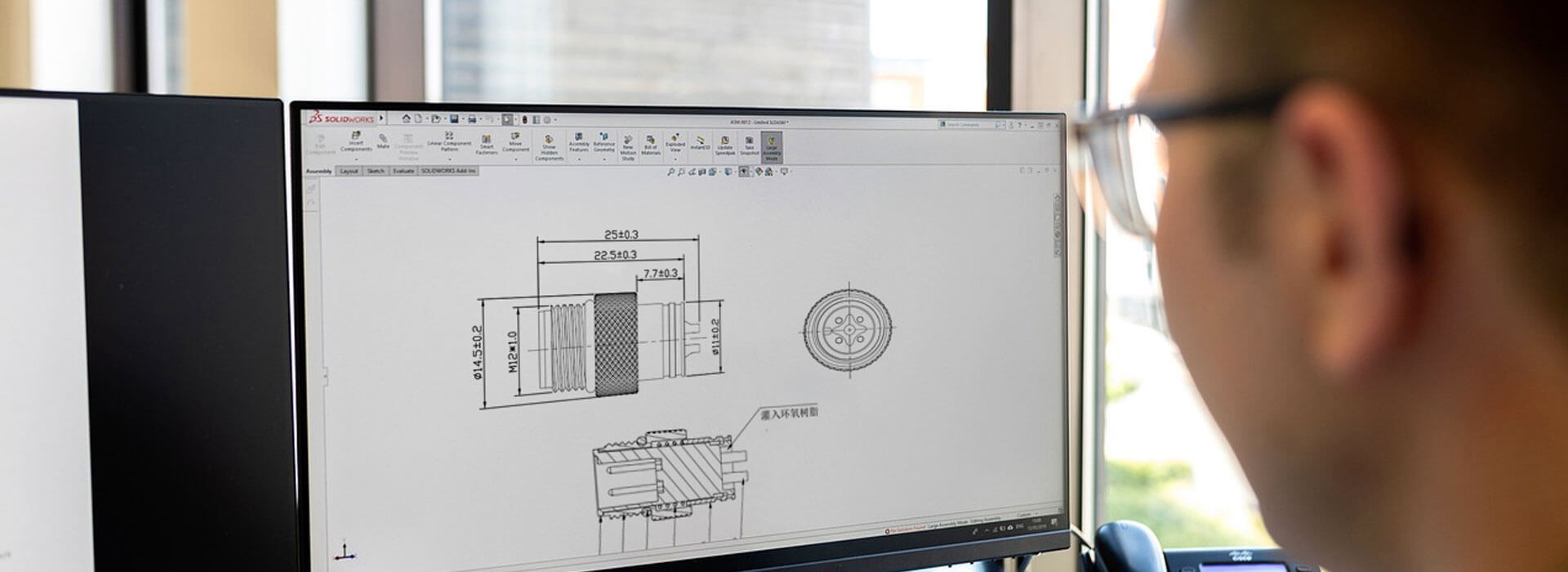
An M8 panel socket needs a defined way to react the turning force applied while its mating collar is tightened or released. That may involve an approved flat, key, mounting arrangement or holding feature. A retaining nut alone does not tell you how rotation is controlled. Identify the load path on the exact socket drawing before relying on internal wires to keep the body still.
Follow the turning force past the front face
Watch which part moves during a connection operation. The cable plug's coupling collar is supposed to turn; the installed panel socket may need to remain stationary. If the socket body follows the collar, that movement reaches whatever is attached behind the panel. A short wired termination can twist, and a rigid connection can be loaded even though the front of the assembly still looks tidy.
This is a mechanical restraint question. Providing enough room to reach the nut is useful, but access does not establish what prevents the socket from turning. Likewise, an environmental seal has a different job from a positive anti-rotation feature. The drawing should make each function identifiable instead of leaving the installer to infer it from a photograph.
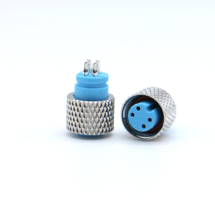
What would count as an anti-rotation feature?
Binder's published M8 installation drawings distinguish a panel opening with flats for anti-rotation from other mounting proposals. That is a useful design example: the body feature and the panel feature must work together. It is not permission to copy Binder's dimensions, mounting thicknesses or tightening values onto a KMYD part.
For a proposed KMYD socket, ask the supplier to mark the feature that carries the reaction into the panel. If the answer is a flat, locate the matching geometry on both drawings. If the installation instead relies on a specified clamping arrangement, request its assembly conditions. A visible flat on the connector body might be intended for a tool; it should not automatically be treated as the approved panel locating feature.
| Question | Evidence to request | What remains unresolved without it |
|---|---|---|
| What locates the body? | Connector and panel drawings showing the engaged locating geometry. | Whether the body can rotate inside the opening. |
| What retains it axially? | The specified mounting parts and assembly instruction. | Whether retention depends on an unlisted washer or other improvised part. |
| What supports the rear connection? | A rear-view assembly sketch showing wires or a board interface. | Whether mounting or mating loads can reach a termination. |
A round opening is not automatically wrong, and a shaped opening is not automatically sufficient. The acceptable arrangement belongs to the selected part and its approved installation. Coating, a substituted washer or a changed panel material can alter the assembly described in that instruction, so these changes need review rather than an assumption that more tightening will compensate.
Leave the internal leads out of the restraint system
Consider an illustrative enclosure with a wired socket behind a small front panel. A technician can see the collar but cannot see the short wires inside. Holding those wires tightly with a cable tie could hide body movement by transferring it into the conductors. That would not provide evidence of a sound panel mounting.
Review the routing with the socket fixed by its intended mounting features. Look for wires that become taut, turn around one another or rub a nearby edge when the body is installed. Any required holding tool should react against the feature identified by the manufacturer, not against the wires, insert or an unsupported circuit board. Whether such a tool is permitted must come from the part's instruction.
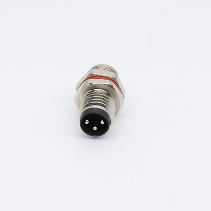
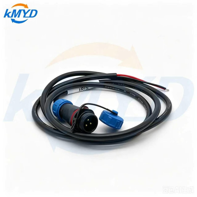
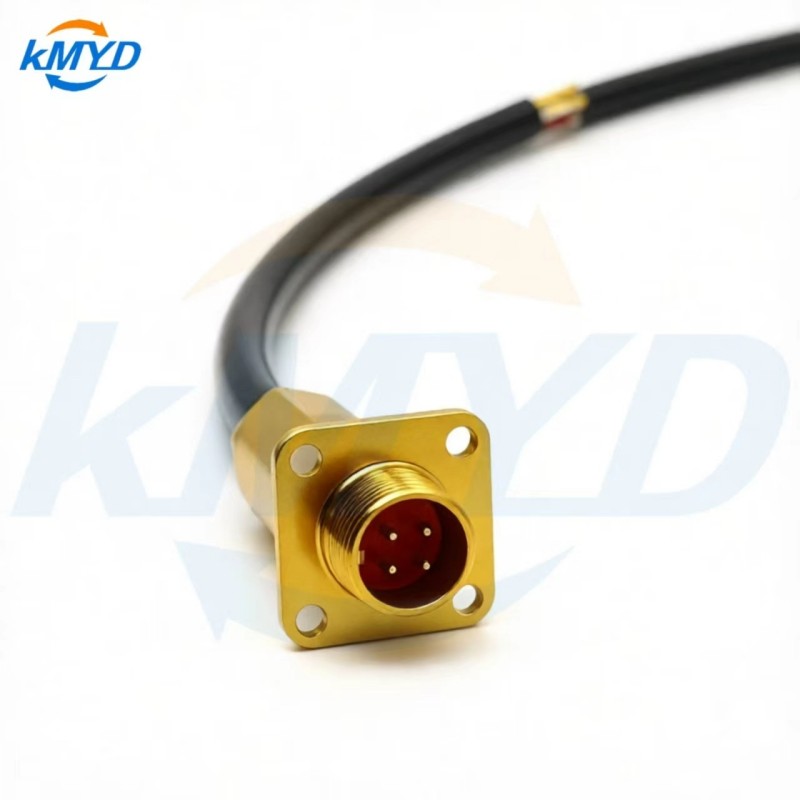
The M8 panel connector listing and the related M8 configuration provide starting points for that discussion. Include the proposed counterpart so the supplier reviews the actual mating operation as well as the socket by itself.
Put one rotation check on the assembly review
On isolated equipment, have the responsible assembler demonstrate the prescribed mating and release operation using the approved panel build. Record whether the socket body moves and whether the rear connection is disturbed. Do not add an improvised overload or repeat-cycle target. If the body turns, stop acceptance and return the drawing, mounting parts and observed movement for review.
The useful deliverable is an annotated front-and-rear sketch identifying the rotating collar, stationary body, reaction feature and protected rear connection. Resolve those four items before the panel drawing is released.


 Tel: +8619924482730
 Email: info@kmydconnector.com
 MP/WhatsApp: +8619924482730
 Manufacturer Address:Baoan District, Shenzhen City, Guangdong Province,China