

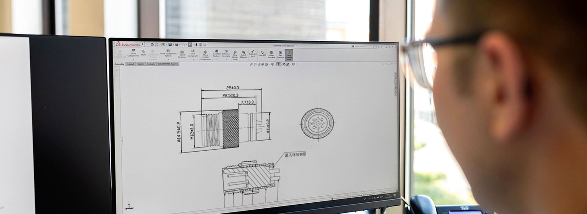
A panel drawing for a waterproof RJ45 connector should identify the cutout, finished panel thickness, sealing surface and complete mounting stack. Tie those details to the exact connector drawing before releasing the panel for manufacture. A housing photograph does not establish a hole diameter, an orientation feature or a permissible thickness. Leave unconfirmed dimensions visibly unresolved and obtain the supplier's installation drawing; do not let a workshop fill those gaps from a sample's approximate appearance.
Separate the connector drawing from the panel drawing
The connector supplier defines its mounting interface. The equipment designer must translate that interface into a manufacturable panel drawing without losing its conditions. Keep the supplier's part number and drawing revision alongside the panel revision so a later connector substitution can be assessed against a known reference.
A general outline dimension is not necessarily a cutout dimension. Request the actual installation view, including any flat, keyway, anti-rotation feature or local clearance specified for the selected part. If a feature is not defined, ask whether it is required. Do not add one solely because a similar-looking connector from another supplier uses it.
Locate the opening from the equipment's defined datums. An isolated hole dimension may be correct while its position places the connector across a folded edge or another sealing interruption. The panel designer should review both the opening geometry and its position relative to the available flat mounting surface.
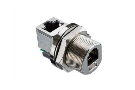
Draw the stack in section, including the finish
Show the connector shoulder, gasket, panel and retaining hardware in their intended order. Label the seal rather than relying on a thin line that could also represent a washer. Distinguish supplied components from parts that the equipment manufacturer must provide, and identify the sealing side of the panel.
| Field | Release question |
|---|---|
| Panel thickness | Does the finished thickness interval satisfy the selected connector's documented mounting limits? |
| Cutout geometry | Are the shape, orientation, tolerances and location datums taken from approved drawings? |
| Seal landing surface | Which face must remain suitable for the specified gasket, and what preparation is required? |
| Mounting parts | Are the gasket, nut and any approved washers individually identifiable in the assembly record? |
State how coating thickness is handled in the dimensional review. A sheet-metal callout before finishing and a finished panel measurement may describe different conditions. Ask the supplier which condition its mounting limits apply to, then make the panel instruction consistent. Do not invent an allowance for paint or plating.
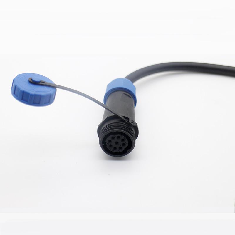
An added washer or reinforcement changes the stack even when the cutout stays the same. Have that arrangement checked against the specified mounting geometry. KMYD describes its circular female RJ45 product as front-fastened, but the listing alone does not define a complete hardware stack for the buyer's enclosure.
Give the gasket a defined landing surface
A mounting seal needs an installation surface consistent with its design. Identify the specified sealing face and review the surrounding panel for burrs, distortion, holes, raised markings or other features that could interrupt it. Follow the connector manufacturer's preparation instructions; do not assume the gasket will compensate for an unspecified surface defect.
The gasket arrangement is part-specific. HARTING's RJ45 bulkhead product information, for example, expressly identifies a flat seal and a particular housing arrangement. It illustrates why mounting components must be named. It does not provide a seal, cutout or rating that can be transferred to the KMYD connector.
Distinguish the housing-to-panel joint from protection of the RJ45 mating face. The assembled equipment needs the applicable conditions for both. A properly fitted panel gasket does not establish that an uncovered front port is protected, and a sealed mating pair does not settle a gap around the panel mounting. Keep these boundaries visible on the installation drawing.
Inspect the first finished panel against the released record
Measure the first panel after the manufacturing and finishing steps defined in the drawing. Compare its opening and local thickness with the specified limits using the agreed inspection method. Record the results against the panel revision, rather than retaining only a photograph of a connector inserted in the hole.
Inspect the sealing land and cut edge before assembly. If the finish is damaged or a burr requires correction, apply the approved manufacturing repair process and recheck the affected feature. An assembler should not enlarge the opening or remove coating simply to make the connector pass through without a drawing disposition.
During the trial installation, confirm that the specified hardware seats as intended. Include a brief clearance check for the fastening tool and actual rear RJ45 plug, boot and cable approach. These checks complement the drawing inspection; they do not replace missing cutout or stack dimensions.
Dimensional acceptance is separate from ingress validation. A panel can match its drawing and still need the agreed environmental assessment of the completed assembly. Record both decisions separately. The release package should contain the connector reference, panel drawing, identified seal stack and first-piece inspection results, with any remaining uncertainty clearly assigned for resolution.
Technical reference: RJ45 bulkhead product information.



 Tel: +8619924482730
 Email: info@kmydconnector.com
 MP/WhatsApp: +8619924482730
 Manufacturer Address:Baoan District, Shenzhen City, Guangdong Province,China