

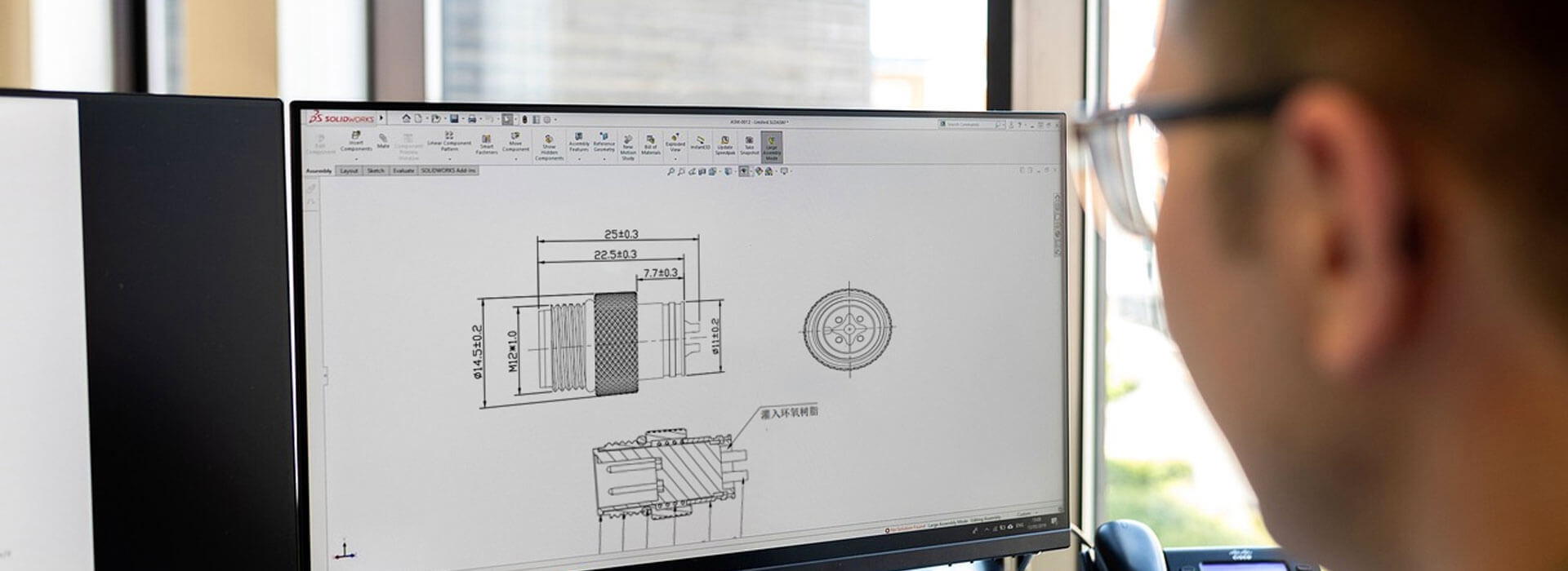
To read a pin diagram for M8 connectors, first find its viewing-direction label. A mating-side view looks into the face that meets the other connector; a termination-side view looks toward the rear connections. Confirm the connector gender, exact insert and orientation before following any contact number. If the drawing does not identify the view, ask for clarification. A familiar pattern, matching wire colors or a photograph of the connector is not enough to establish the wiring.
“Female connector” does not tell you which side is shown
Gender identifies the mating contacts. Viewing direction identifies the observer's position. A female connector can be illustrated from the socket face, from its rear terminals or in a side view. Those descriptions answer different questions and need to stay together when a diagram is copied into a cable drawing.
A useful caption might identify a female M8 insert, the applicable part reference and a view into its mating face. It should also provide an orientation feature where one is needed. The corresponding male drawing needs its own caption. Do not carry the female picture across to the male end simply because both belong to one cable assembly.
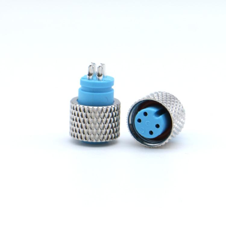
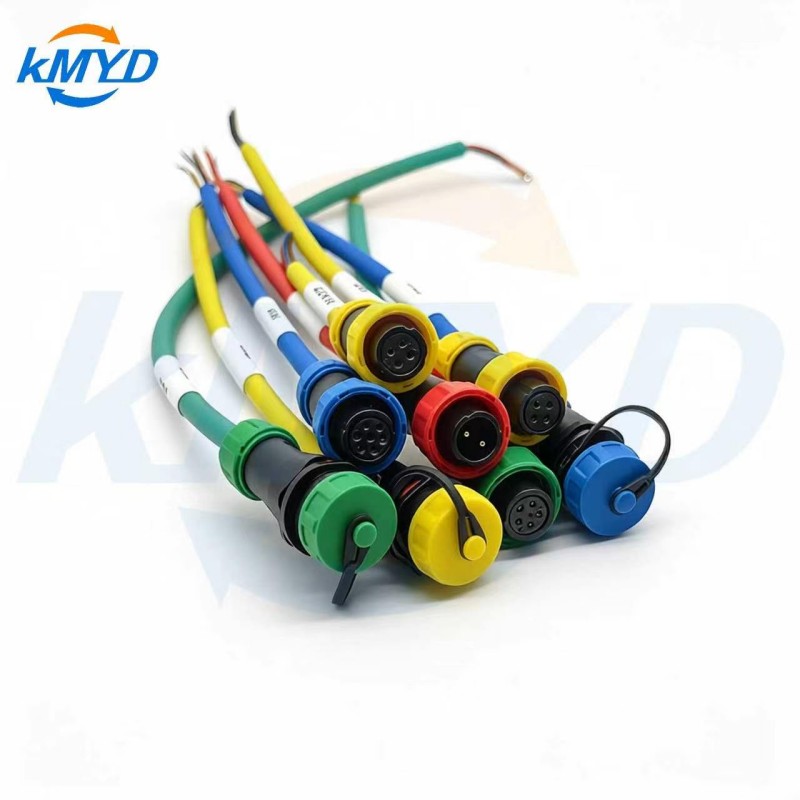
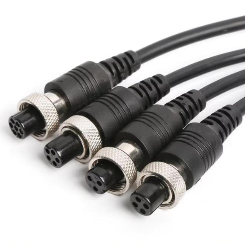
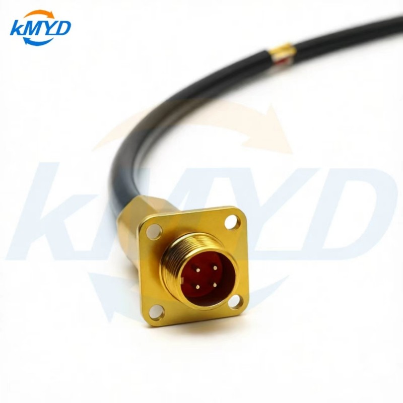
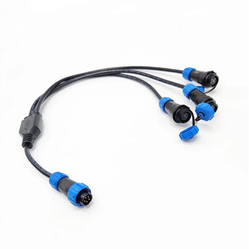
KMYD's M8 female connector listing is a relevant product reference for an inquiry. Use the photograph to identify the configuration you are discussing, then obtain the matching contact drawing. Do not assign signals by the contact positions visible in a catalog image.
Why a correct pattern can appear reversed
Looking at the opposite side of the same insert changes the apparent arrangement. Turning the connector in your hand can change the orientation again. If a technician copies positions from a front view while working at the rear, the resulting termination can be wrong even though the number of contacts matches.
Resolve the perspective before resolving the signals. Find the stated view, locate the reference feature shown by the manufacturer and identify the contact numbers from that drawing. Keep the drawing in its documented orientation while comparing it with the part. An unlabelled rotation or mirror operation in an image editor can remove the very information needed to interpret it.
Do not repair an unclear drawing by guessing. Ask the supplier to return a drawing with the view and contact numbering explicitly identified. An annotated response is more useful for future production than a verbal explanation that never reaches the assembly document.
Manufacturer documentation can make this distinction explicit. For example, binder labels the contact-arrangement image for a specific M8 male panel connector as “Plug-in side.” That label belongs to that product drawing; it illustrates the importance of a stated view, not a pin map that can be transferred to every M8 connector.
Use the drawing that answers the question
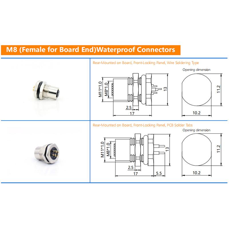
A connector documentation package may contain several diagrams that look related. They serve different purposes. A mounting drawing can establish where a part sits in a panel without establishing which contact carries a signal. A cable connection table can establish a net relationship without showing the physical position of either terminal.
| Document | Use it to identify | Information still needed |
|---|---|---|
| Contact arrangement | Numbered contact positions for a stated connector and view. | The required signal or wire assigned to each contact. |
| Cable connection table | Which contact at one end connects to which contact at the other. | The physical contact diagrams and their viewing directions. |
| Panel or outline drawing | The illustrated mounting features and mechanical envelope. | Electrical correspondence and any separately documented contact arrangement. |
| Equipment wiring diagram | The functions required by the connected equipment. | The exact connector version used to implement those connections. |
Keep the two cable ends separate on the drawing
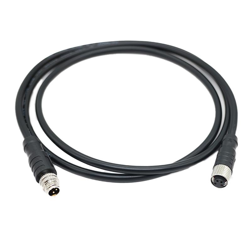
Give each end an identifier, such as End A and End B, and put that identifier beside its connector reference. Record the gender and viewing direction beside each contact diagram. This is particularly useful when the assembly combines a cable connector with a panel connector, or when the cable leaves one end at an angle.
Then describe the electrical relationship independently. For every required connection, identify the contact at End A, the conductor identification and the destination at End B. Add shield or drain connections only where the approved design requires them. Similar colors do not establish the same circuit, and a connector's housing appearance does not identify its signal assignment.
Do not assume that identical numbers must connect straight through. The equipment wiring requirement controls that decision. If the requested assembly crosses, splits or leaves a circuit unused, show the intended relationship explicitly rather than expect the assembler to infer it from the connector illustrations.
Keep the connector-view labels beside the diagrams when issuing a cropped detail or sending a drawing excerpt. Include the document revision in the excerpt as well. A clear full drawing can become ambiguous when the title block or small viewing-direction caption is missing from a screenshot.
Close the ambiguity before the first termination
Review one complete connection from the equipment requirement to the cable table, then to the stated contact view at each end. If any part of that chain depends on an assumption, mark it for confirmation before building the assembly. The exercise is a drawing review, not permission to probe or rewire powered equipment.
Ask for an unpowered wiring check against the approved connection table before installation. Such a check can establish whether the documented endpoints are connected as intended; it does not prove that the underlying equipment requirement was correct. Keep both the design confirmation and the assembly result with the accepted drawing revision.
For an M8 connector inquiry, send the equipment-side reference and the diagram that is causing uncertainty. Request the exact matching contact drawing with a named viewing direction. That gives the person selecting the part and the person terminating the cable the same reference.
Drawing-label example: binder's M8 product page with a plug-in-side contact-arrangement label. This is a documentation example, not a compatibility claim for KMYD products.




 Tel: +8619924482730
 Email: info@kmydconnector.com
 MP/WhatsApp: +8619924482730
 Manufacturer Address:Baoan District, Shenzhen City, Guangdong Province,China