SP20/SD20 Right-Angle Docking Connector
How to Mount an M12 Right-Angle Socket on a PCB
In industrial controllers, sensor modules, robotics, and vehicle electronics, M12 right-angle sockets are widely used as compact and reliable board-level connectors. Compared with straight connectors, right-angle M12 sockets allow more flexible cable routing and help reduce overall enclosure height, making them ideal for space-constrained applications.
However, achieving long-term reliability requires careful consideration of PCB layout, soldering methods, and mechanical reinforcement. This article explains the key design and installation considerations for mounting M12 right-angle connectors on printed circuit boards.
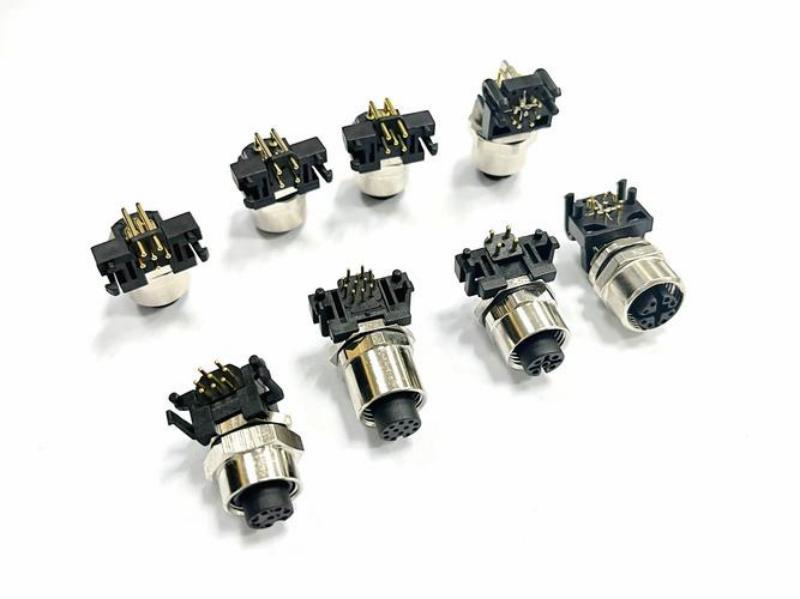
Understanding the Structure of M12 Right-Angle Sockets
An M12 right-angle socket changes the cable exit direction by 90 degrees relative to the PCB surface. This design improves internal space utilization and simplifies wiring inside compact devices.
Most right-angle M12 sockets are available in two termination styles:
Through-Hole PCB Pins
The connector uses through-hole pins that are inserted into plated PCB holes and soldered by wave soldering.
SMT Surface-Mount Type
The connector uses surface-mount terminals suitable for automated reflow soldering and high-density PCB layouts.
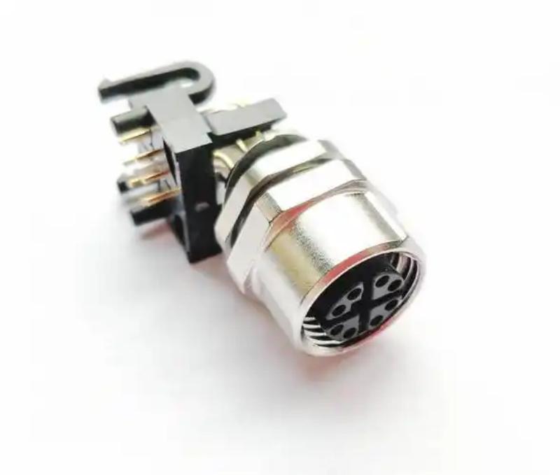
PCB Layout and Footprint Design
Selecting the Cable Exit Direction
Right-angle connectors are typically available in left-exit and right-exit versions when viewed from the mating face. Designers should select the orientation based on enclosure structure and internal component placement to avoid cable interference.
Some connector models also support rotatable flanges, allowing flexible angle adjustment during assembly.
Verifying PCB Footprint Dimensions
The PCB footprint should strictly follow the connector datasheet specifications.
Key dimensions include:
- Pin pitch: usually 2.5 mm or 2.54 mm
- Positioning posts: typically 1.5–2 mm diameter plastic pegs for alignment
- Flange mounting holes: commonly M2 or M2.5 screw holes for panel fastening
Positioning posts help prevent connector movement during soldering and improve alignment accuracy between the connector and enclosure panel cutout.
Soldering Process Considerations
Wave Soldering for Through-Hole Connectors
Through-hole M12 right-angle sockets are commonly used in high-volume industrial production and are compatible with wave soldering processes.
Important considerations include:
High-Temperature Housing Materials
Connector insulators should withstand peak temperatures up to 260°C. LCP and high-temperature PA66 materials are recommended to prevent deformation or blistering during soldering.
Flux Protection
During wave soldering, flux residue may enter the contact area. Choosing connectors with sealed flanges can help reduce contamination risks.
Typical Wave Soldering Parameters
- Preheating temperature: 80–100°C
- Wave temperature: 245–260°C
- Soldering time: 3–5 seconds
Reflow Soldering for SMT Connectors
SMT M12 sockets are increasingly used in compact industrial Ethernet and high-speed signal applications.
Key requirements include:
Pin Coplanarity
All SMT terminals should maintain coplanarity within 0.1 mm to prevent cold solder joints or insufficient solder wetting.
Solder Paste Design
Recommended solder paste thickness is 0.15–0.2 mm, with stencil openings optimized according to terminal geometry.
Reflow Profile
- Peak temperature: 240–260°C
- Reflow duration: 60–90 seconds
Mechanical Reinforcement and Stress Relief
Panel Mounting
For panel-mounted devices, the connector flange should be mechanically fixed to the enclosure using screws. This allows insertion and extraction forces to be transferred to the panel instead of the PCB solder joints.
This design significantly improves long-term reliability in applications with frequent cable plugging and unplugging.
Additional Reinforcement Methods
For internal board-to-board or non-panel-mounted applications, extra reinforcement is recommended:
- Apply epoxy adhesive between connector body and PCB
- Use connectors with additional support posts or mounting legs
- Add PCB reinforcement structures around the connector area
These measures improve vibration resistance and reduce solder joint fatigue.
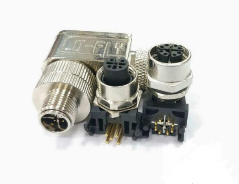
Typical Industrial Applications
Industrial Remote I/O Modules
Many IP67-rated distributed I/O modules integrate multiple M12 A-coded right-angle sockets directly onto the PCB. Through-hole connectors combined with wave soldering provide efficient mass production and stable field performance.
In automotive welding line applications, properly mounted connectors can operate reliably for over 20,000 hours without solder cracking.
Robot Controllers and Industrial Ethernet Devices
In collaborative robot controllers and industrial Ethernet systems, M12 X-coded right-angle connectors are often installed using SMT technology.
Additional PCB reinforcement and precise positioning structures help ensure stable Gigabit Ethernet transmission under vibration conditions.
In vibration testing environments ranging from 10–55 Hz, properly soldered connectors can maintain extremely low signal error rates.
Common Installation Problems and Solutions
| Problem | Possible Cause | Recommended Solution |
|---|
| Connector tilts after soldering | Loose fit between positioning post and PCB hole | Tighten PCB hole tolerance to ±0.05 mm |
| Solder joint cracking | Plugging force transferred to solder joints | Add panel fastening or adhesive reinforcement |
| Cold solder joints after reflow | Poor coplanarity or insufficient solder paste | Use connectors with ≤0.1 mm coplanarity |
| Flux contamination | Flux enters contact area during wave soldering | Use sealed connectors or add cleaning process |
Conclusion
Proper installation of M12 right-angle sockets on PCBs requires coordinated consideration of connector footprint design, soldering processes, and mechanical reinforcement.
Through-hole versions are ideal for wave soldering and high-volume industrial production, while SMT versions support compact and high-density electronic designs. Combining reliable panel fixation with proper stress-relief methods can significantly improve connector durability in demanding industrial environments.
With optimized PCB design and assembly processes, M12 right-angle connectors can provide stable performance under vibration, repeated mating cycles, and harsh operating conditions.
For related guidance on PCB-mounted M12 socket selection and layout, see PCB-Mounted M12 Socket Connectors for Ethernet Switch Panels. For a broader view of circular connector options, review the Aviation Plug Connectors range.




 Tel: +8619924482730
 Email: info@kmydconnector.com
 MP/WhatsApp: +8619924482730
 Manufacturer Address:Baoan District, Shenzhen City, Guangdong Province,China