

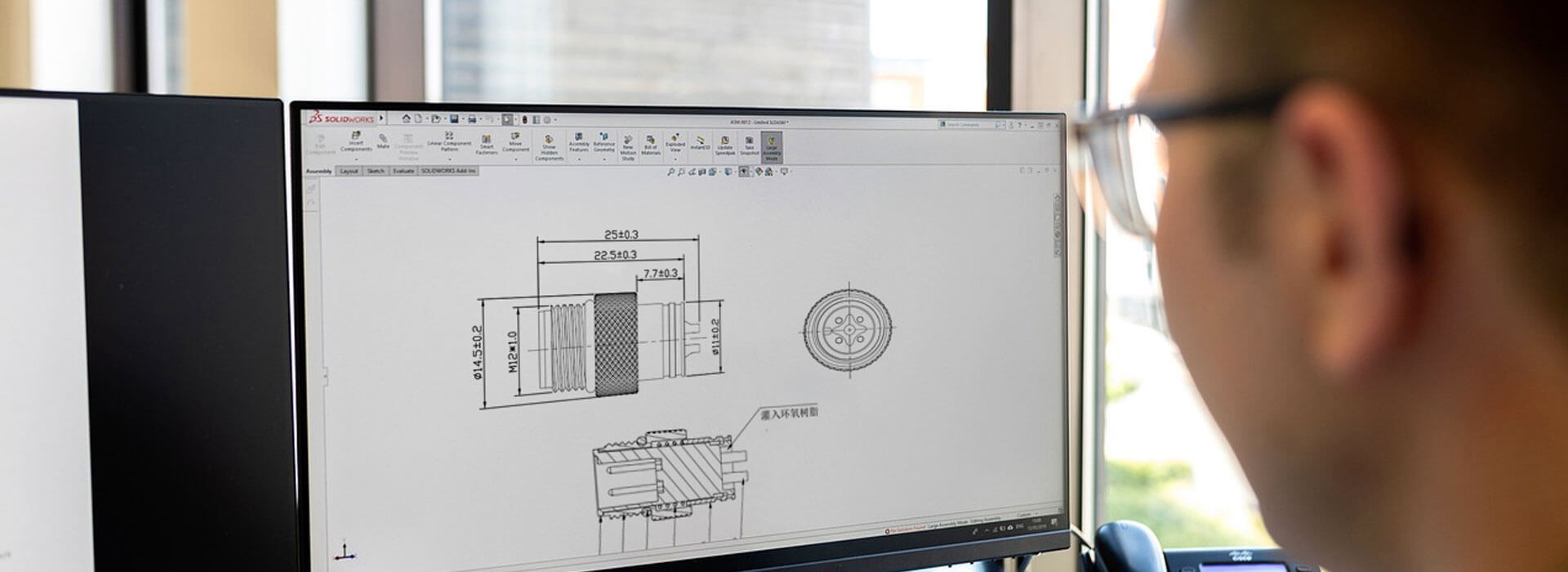
For a low-voltage DC supply, the voltage lost in custom cable assemblies depends on load current and resistance around the complete outgoing-and-return circuit. The useful result is the voltage left at the device when it draws current. Start with the lowest source voltage the system must tolerate, subtract the calculated wiring loss, and compare what remains with the device's minimum input requirement. A nominal supply label cannot make that comparison for you.
Give the receiving device a voltage budget
Suppose a sensor works on a short bench lead but resets after installation on a longer route. Before declaring the new cable defective, ask how much supply voltage the equipment can afford to lose. The power source has an operating range, the device has an input range, and the wiring consumes part of the difference.
Use the minimum source-terminal voltage under the relevant demand, not the unloaded setting. Use the device's required input during the event being assessed; a startup requirement may differ from steady operation. Then identify the current that flows during that same event. Combining an optimistic source value with an average current can conceal the condition that causes the reset.
| Assumed quantity | Example value |
|---|---|
| Lowest voltage at the source terminals under load | 23.0 V |
| Minimum voltage required at the device | 22.0 V |
| Current during the assessed operating condition | 2.0 A |
| Total resistance of both conductors and their connections | 0.40 ohm |
For this simplified resistive circuit, loss equals current multiplied by resistance: 2.0 A × 0.40 ohm = 0.80 V. The device receives 23.0 − 0.80 = 22.20 V, leaving 0.20 V above its assumed minimum. That is a small remaining allowance, not a measured result or a complete design approval.
If an extension increases the total circuit resistance to 0.60 ohm while the other assumptions stay unchanged, the loss becomes 1.20 V. Only 21.80 V reaches the device, below the assumed requirement. The extension can therefore change the voltage decision without changing the nominal supply or connector family.
Count the return path and the connections
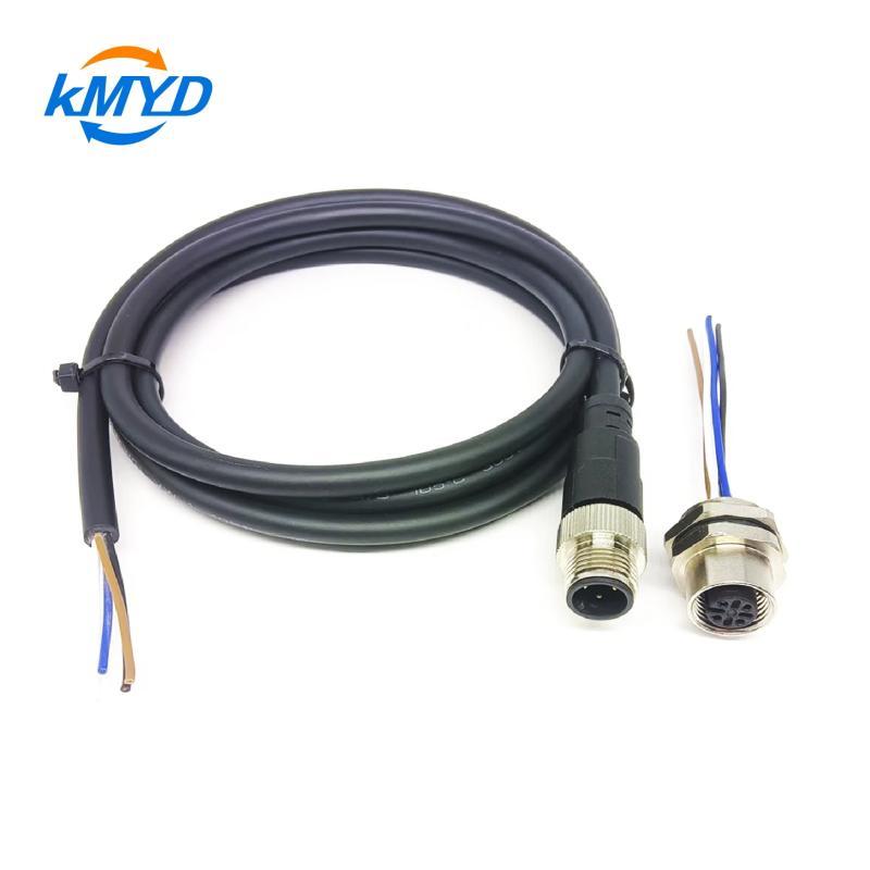
The resistance in that example is a loop value. It includes the outgoing conductor, return conductor, mating contacts and terminations within the defined boundary. A cable data sheet may give resistance per unit length for one conductor. Multiplying that figure by a one-way route length does not account for both sides of a two-wire supply.
Also distinguish a wire-only estimate from an assembled-path estimate. Intermediate plugs, splices and terminal connections can add resistance. Obtain values appropriate to the proposed cable length, conductor and relevant temperature condition, then identify which connection contributions are included. Do not add a contact allowance twice if the measured assembly value already contains it.
A shared return deserves a separate line in the calculation. If several devices use that segment simultaneously, its voltage loss depends on their combined return current. For a branched route, calculate each shared segment using the current through that segment, then add the losses along the path to the device being assessed. One device's individual current cannot represent every part of the harness.
The example's theoretical resistance ceiling is the available 1.0 V divided by 2.0 A, or 0.50 ohm. At that ceiling there is no allowance left for other variation. The equipment designer must decide the required margin and which worst-case conditions belong in the budget; the arithmetic does not supply a universal acceptance limit.
Compare voltages during the same operating event
An open-circuit reading at the far end can look satisfactory because the measuring instrument draws very little current. It does not reproduce the loss when the device starts or operates. The useful comparison captures source voltage, device voltage and the load condition together, using the equipment's approved measurement procedure.
If the source itself sags during startup, attributing the entire reduction to the cable would be misleading. Conversely, a stable source with a larger-than-expected difference at the device points toward the intervening path. Fluke's voltage-drop guidance distinguishes losses on the supply side and return side; both contribute to the voltage available to the load.
Match the recording method to the duration of the event. A brief startup dip may be missed by a slowly updated display. Have the responsible technician select appropriate measurement equipment and access points, then retain the operating state with the readings. A simple resistance budget leaves fast transient behavior and control-loop interactions outside its model.
Choose a change that addresses the loss
Where conductor resistance dominates, options may include a shorter route or a suitable larger conductor. Where one connection accounts for an unexpected loss, investigate that connection against its assembly requirements. Increasing conductor size will not repair a poor termination elsewhere.
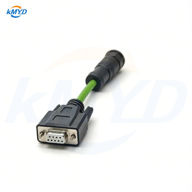
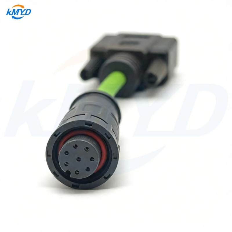
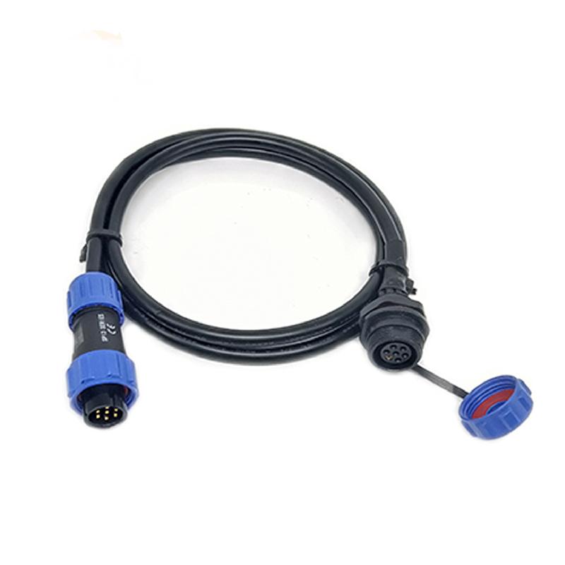
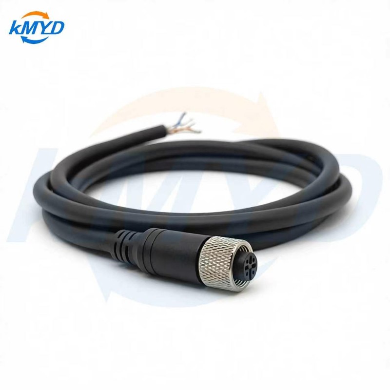
Check the consequences of a proposed cable change. A larger conductor must remain compatible with the selected termination, jacket size and cable entry. Thermal current capacity is a separate requirement: passing the voltage budget does not establish it. KMYD's custom cable offering and M16-to-DB9 assembly provide inquiry routes for comparing proposed constructions.
Do not simply raise the source setting until the far-end reading improves. That can change the voltage seen under lighter loading or by nearer devices. A supply designed for remote sensing may compensate within its documented limits; Keysight explains that technique, but it is an equipment feature to review, not a property supplied by an ordinary cable.
For the next sample, keep the voltage budget beside one loaded measurement record. If the observed loss differs from the estimate, locate the missing resistance or operating assumption before changing the design. The decision becomes specific: this route leaves enough voltage at this device during this defined demand.
Background: Fluke on supply- and return-path voltage loss; Keysight on lead resistance and remote sensing.



 Tel: +8619924482730
 Email: info@kmydconnector.com
 MP/WhatsApp: +8619924482730
 Manufacturer Address:Baoan District, Shenzhen City, Guangdong Province,China