

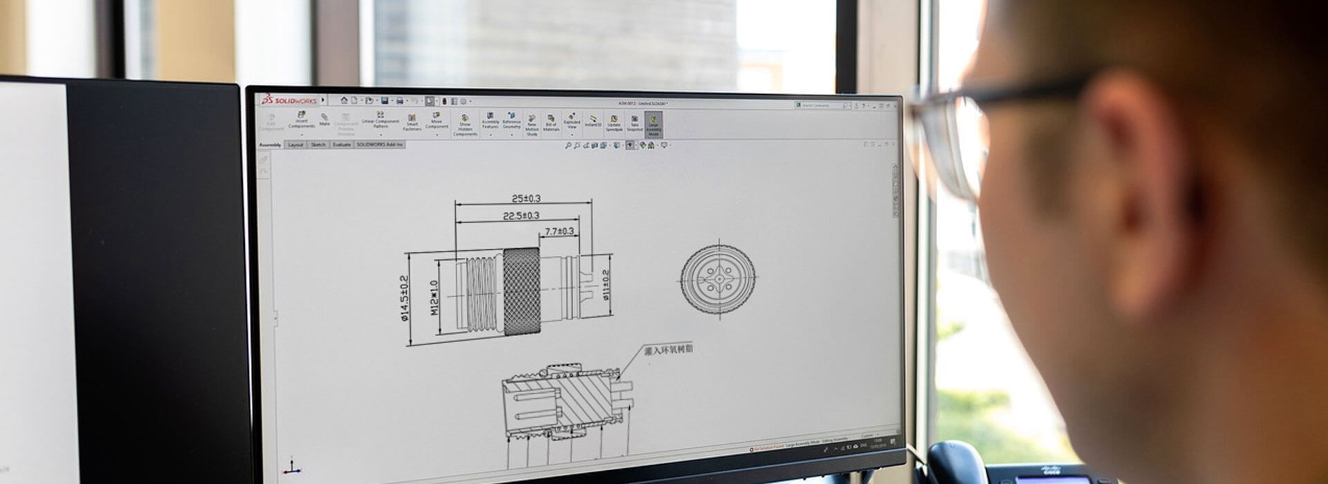
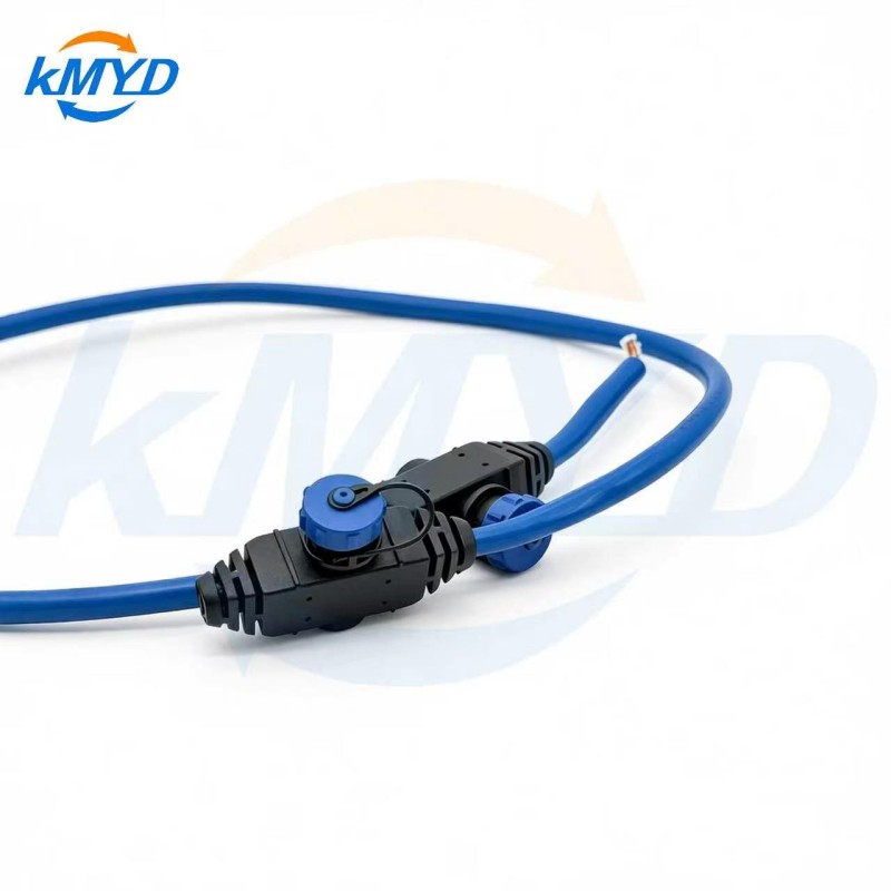
A branch in custom cable assemblies needs two definitions: what happens to the circuits, and how the cables leave the junction. A Y-shaped outline cannot tell a manufacturer whether conductors are joined, kept separate or simply gathered under a common sleeve. Settle that distinction first. Then agree the junction construction, its restraint and environmental boundary, with enough detail to inspect the finished build without guessing what is hidden inside.
Start with what the junction actually does
Imagine one incoming cable and two outgoing legs. One design might distribute a common supply to both destinations. Another might separate independent circuits from a multicore cable into two connectors. The outside shape could be similar, but joining the wrong conductors would change the circuit completely. A sketch that says only “split cable here” leaves the most consequential choice unresolved.
Give each junction an identifier and show the intended electrical connections separately from the physical outline. Use an endpoint list or netlist: a record of which contact or conductor connects to which others. List every intended common connection, every independent path and any conductor that stops at the junction. Wire color can support identification, but it should not be the only definition of circuit function.
Conductors leave a shared covering. They may remain electrically separate throughout.
Specified conductors are deliberately joined into one electrical connection.
Separate finished cables travel together without necessarily sharing any internal connection.
Keep these descriptions distinct on the drawing. For a data interface, confirm with the equipment documentation that the proposed topology is permitted; adding a branch is not automatically equivalent to extending a point-to-point cable. A supplier can build a wiring arrangement without that arrangement being suitable for the attached devices.

Describe the exits as an installed shape
The branch lengths may be correct while the junction still occupies the wrong space. Show the incoming route, the direction each leg must leave and any nearby bracket, enclosure edge or moving part. Identify which faces or surfaces can be used for support and which areas need clearance. Refer to the separate length drawing for dimensions; the junction view has the different job of explaining how the bundle changes direction.
Consider installation order. Can the completed junction pass through the intended opening, or must the harness be positioned before a cover is attached? Can one branch be disconnected without pulling the other branch taut? A physical mock-up of the occupied space can expose these conflicts before the supplier commits to a compact-looking outer form.
Describe where the installation restrains each cable. Do not leave an internal electrical joint to serve as the unspecified anchor for a leg that will be pulled during servicing. Ask the assembly supplier to explain how the proposed junction handles those loads, and agree any required verification conditions. Neither a neat outer sleeve nor a large molded body proves that requirement has been met.

Mark where the environmental requirement applies
If the assembly crosses a wet or dirty area, identify whether the junction itself is exposed. Include the cable entries and the transition between the covering and each jacket. An ingress rating attached to an endpoint connector does not establish the protection of a newly designed junction elsewhere in the harness.
Also identify whether the joint stays fixed, experiences movement, or encounters oils or cleaning agents. Request a construction proposal for those stated conditions. Avoid specifying an appearance, such as “black molded Y,” as a substitute for the materials, interface preparation and evidence needed to support the requirement.
KMYD's M8 category includes branches among the details to provide for custom cable work. Its custom cable listing supplies a starting point for discussing endpoint and cable options. Neither page supplies an approved construction drawing for the junction in your project.
Review the inside and outside together
- Trace each intended circuit through the junction and identify every deliberate common connection.
- Compare that electrical definition with the supplier's proposed internal construction.
- Place the sample or agreed envelope in the installation and check branch exits, support and assembly access.
- Identify the records that demonstrate the hidden work and the checks that assess the finished junction.
Close the review by asking the electrical designer and mechanical installer to mark the same junction view. Their comments should resolve two different questions on one controlled drawing: does it connect the intended circuits, and can that construction occupy the intended space?
Construction background: Molex parallel splice connectors. The drawing review above is a proposed procurement method, not a prescribed splice process.



 Tel: +8619924482730
 Email: info@kmydconnector.com
 MP/WhatsApp: +8619924482730
 Manufacturer Address:Baoan District, Shenzhen City, Guangdong Province,China