

An M8 connector can fit a panel perfectly and still be impossible to service once neighboring cables, guards and internal wiring are installed. Check the space needed to release the coupling, withdraw the plug and replace the panel component as separate operations. The useful question is not simply whether the connector fits the opening: can the planned maintenance job be completed on the finished equipment using the specified tools, without loading the contacts or dismantling unrelated connections?
Decide which part maintenance must be able to remove
Disconnecting a cable from outside the enclosure is one job. Replacing the mounted socket is another. The first may require only access to the coupling and room to withdraw the plug; the second may also require access to a retaining nut, internal wires or a board assembly. Write down which job the equipment design must support.
Define the state in which that work will happen: machine isolated, access cover removed, surrounding cables still connected, or a module taken out of its enclosure. A design that can be serviced after removing a module may be acceptable. It becomes a problem when the maintenance instructions assume the same operation can happen in place.
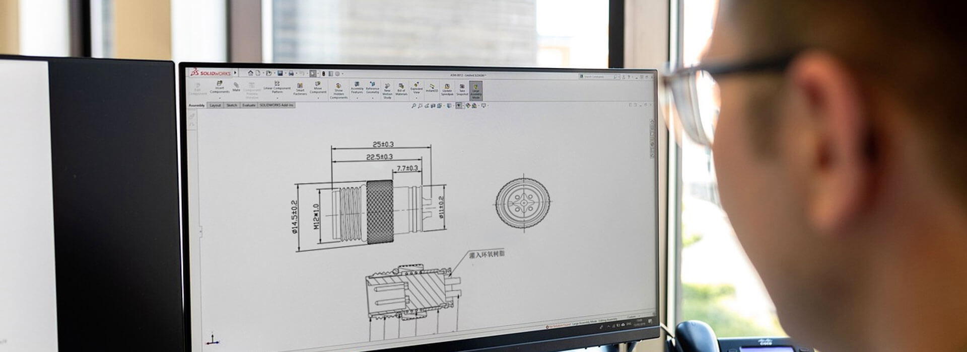
Use an actual connector drawing and the intended mating cable to review access. The M8 designation does not supply a service clearance, and a photograph cannot establish the panel opening or tool size. Keep those values tied to the selected parts and equipment arrangement.
Follow the tool and the plug through their full movement
In a densely populated panel, a tool may reach a coupling at one angle but lack room to turn. Fingers may touch the ring but have insufficient purchase to release it as intended. Evaluate the complete movement, including insertion and removal of the specified tool. Do not plan on gripping the cable jacket or using a tool on a surface the connector instructions do not identify for that purpose.
Next follow the unmating movement. A plug can clear the thread yet remain trapped by a neighboring housing or bracket. A right-angle cable can need a different removal path from a straight one, even when both fit while connected. Include the cable behind the plug in the review so that withdrawing it does not require an excessively tight bend.
Finally, examine the replacement path. The cable brought to the machine must be able to reach the port along the service route, not only along the route used during factory assembly. If another cable must be moved temporarily, make that dependency explicit and check how it will be identified and restored.
The rear face can become the real obstruction
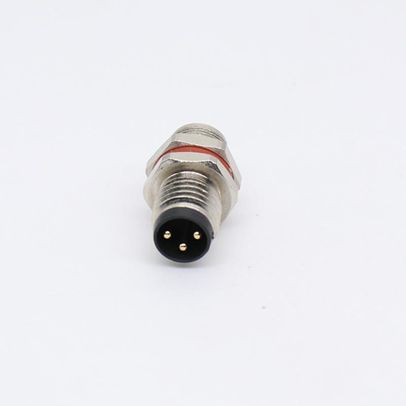
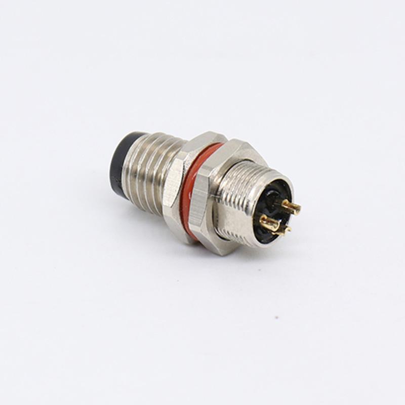
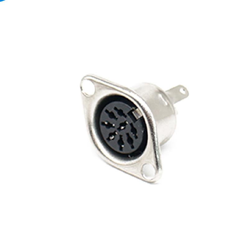
A front-accessible connector is not necessarily replaceable from the front. Establish which side carries the mounting hardware and which direction the selected component must travel during removal. Front and rear fastening are separately identified options in manufacturers' M8 ranges; they are not interchangeable descriptions of the same service operation.
For a wired connection, examine the internal route and termination access. There must be an agreed way to disconnect or move the wiring before extracting the component. Extra wire length is useful only if it can be stored without abrasion, pinching or interference. Do not reserve a loop by allowing unsupported wires to bear the connector's movement.
If the part is attached to a circuit board, include the board's removal sequence in the service review. A connection that relies on board removal should be documented that way. This does not require changing the board footprint; it requires recognizing what maintenance will actually remove.
Run a service trial with the panel populated
A bare-panel sample cannot reveal every obstruction. Assemble the relevant neighboring connectors, cable supports and covers in a representative, isolated equipment mock-up. Use the intended mating plug and the permitted tool. A simple recorded trial can show a conflict that a front elevation misses.
- Identify the port. Confirm that its label remains readable when all nearby cables are fitted and that maintenance can distinguish it from similar connections.
- Release and withdraw. Demonstrate the intended coupling operation and plug removal without pulling on the cable or forcing adjacent connectors.
- Replace the intended service unit. Check the agreed rear access, removable covers and wiring disconnection sequence for a panel-component replacement.
- Restore the installation. Confirm that supports, seals, covers and identification can be returned to their specified arrangement, followed by the equipment's required checks.
Record an obstruction as a specific action that cannot be completed, rather than simply marking the connector “too close.” That makes the design response clear: relocate a support, revise the access opening, choose an appropriate outlet arrangement or change the documented service unit.
Add a service note to the layout drawing
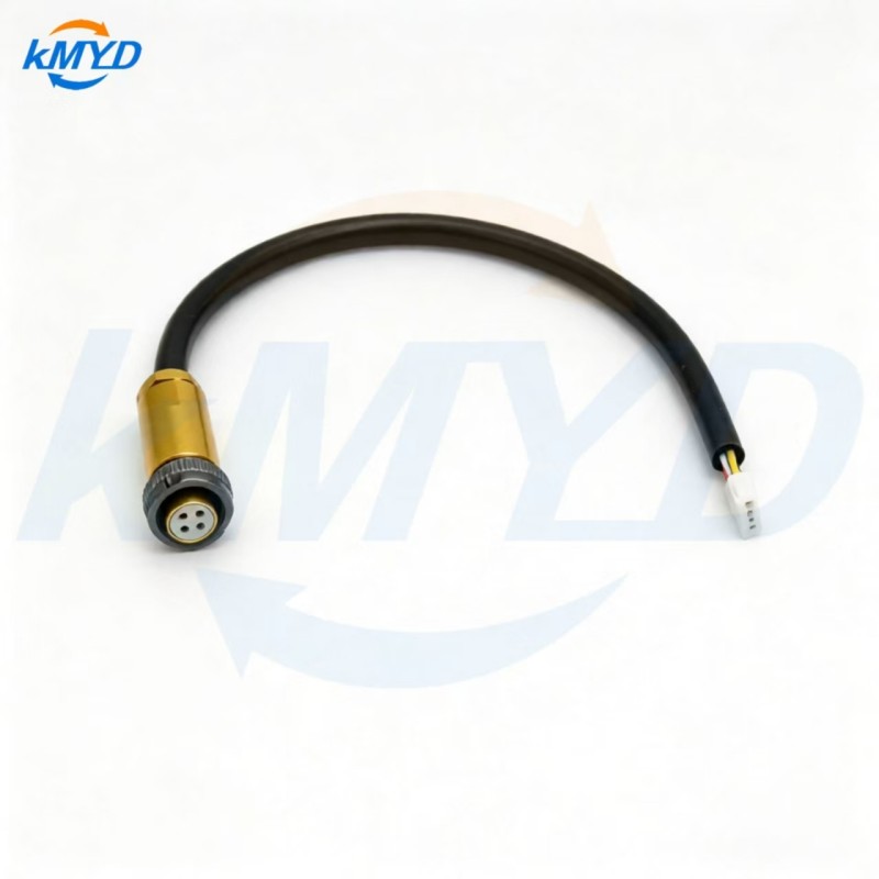
Alongside the exact connector drawing, identify the removable unit, the access side, the approved tool and any cover that must be opened. Include a photograph of the successful populated-panel trial. For KMYD's M8 panel connector configuration, request the matching outline and mounting instructions before freezing that arrangement. Acceptance should mean that the specified service job was demonstrated, not merely that the connector passed through the panel opening.
Reference for mounting terminology: Same Sky circular connector range, which distinguishes front and rear fastening. Its dimensions and product approvals do not apply to the illustrated KMYD component.



 Tel: +8619924482730
 Email: info@kmydconnector.com
 MP/WhatsApp: +8619924482730
 Manufacturer Address:Baoan District, Shenzhen City, Guangdong Province,China