

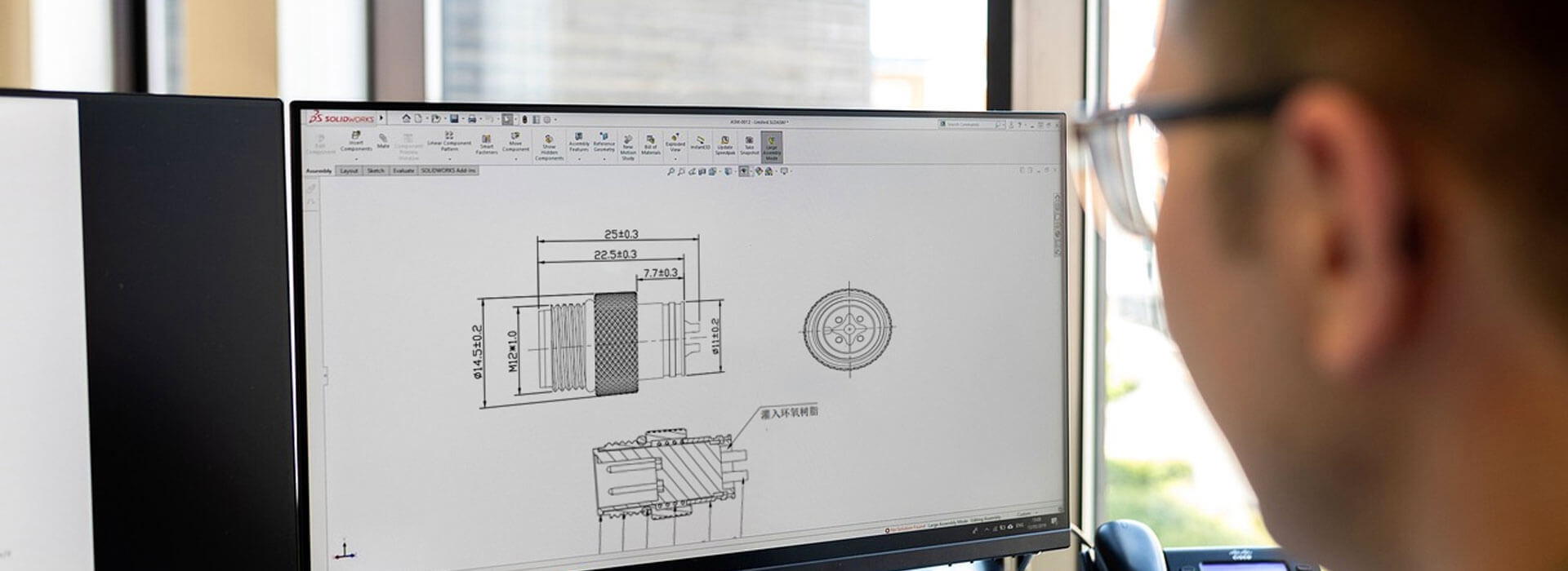
Replacing M16 connectors requires more than matching the number of contacts. Confirm the mating interface, contact layout and key position, then check the mounting, wiring and cable entry against the equipment you intend to keep. The old plug and its socket form a pair: identifying only the removable half leaves an important question unanswered. If the original part number cannot be recovered, ask for a documented comparison and a sample fit check before approving a substitute.
Identify the connection that must stay in service
Start by deciding what is being replaced: a cable plug, a panel receptacle or the complete cable. This determines the fixed reference. When the panel socket will remain in place, its exact interface controls which new plug may be considered. When both halves can change, you have more options, but the enclosure and wiring still need review.
Record the equipment model, connector markings and available purchasing records. Photograph the disconnected mating faces, the coupling and the rear termination area where accessible. Keep the original assembly intact while identifying it. A damaged contact or broken key may hide a feature that would otherwise distinguish the part.
Send the supplier the two part references together. If only one is known, say which one. A request for an “M16 replacement” should identify the equipment-side part that the proposed replacement must mate with, rather than leaving the supplier to assume a matching pair from its own range.
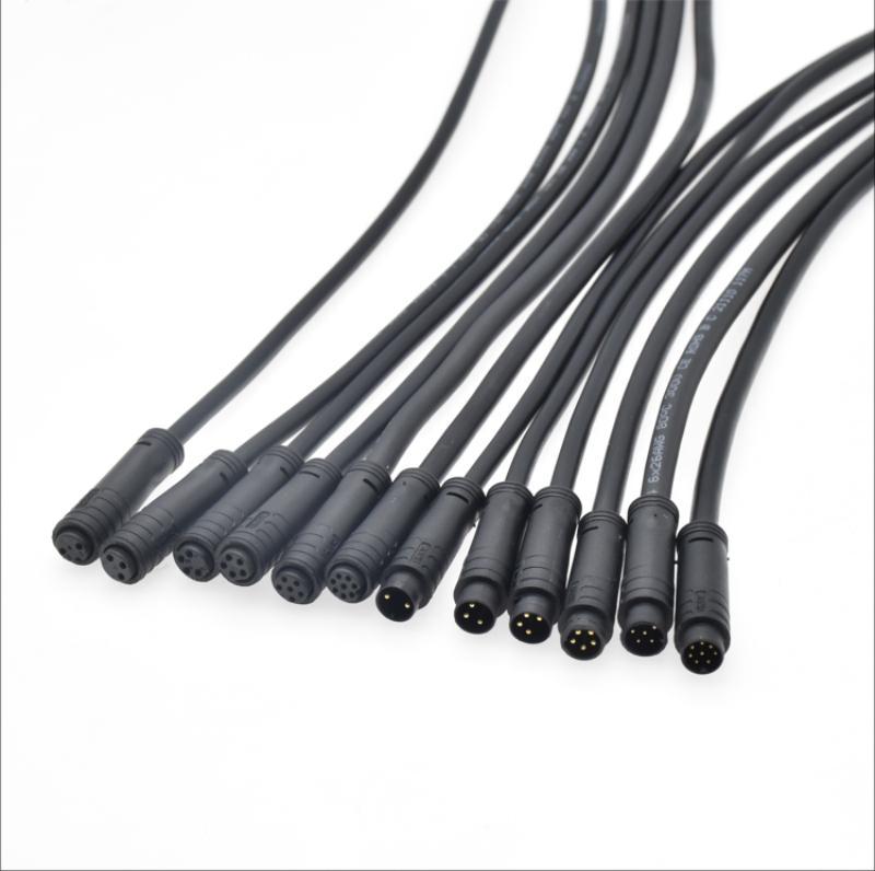
Put both interface drawings side by side
A matching contact count narrows the search, but it does not complete it. Compare drawings of the retained part and the proposed replacement with the viewing direction clearly marked. Check the contacts relative to the key, not relative to how a photograph happens to be rotated.
| Feature | Comparison needed | Evidence to request |
|---|---|---|
| Contact arrangement | Contact positions, sizes and numbering relative to the key | Identified mating-face drawings for both halves |
| Coupling | Thread specification, engagement and locking arrangement | Interface dimensions and the intended mating-part reference |
| Keying | Key or groove position, shape and any alternate insert orientation | A dimensioned interface drawing, rather than pin count alone |
| Sealing | Seal location, mating surfaces and installed conditions | Assembly instructions and protection evidence for the proposed pair |
KMYD's M16 connector range is a place to identify candidate configurations. Its series guidance also distinguishes thread size from the other mating features. Ask for the particular variant's drawing; a category name or a range of available contacts does not establish interchangeability.
A mating match can still leave a mounting problem
For a panel receptacle, compare the mounting opening, anti-rotation feature, panel thickness range, nut and seal arrangement. The coupling interface and the panel mounting interface have different jobs. Do not derive the panel cutout from the M16 name or assume that two receptacles use the same mounting hardware.
Then look behind the panel. A longer rear termination may clash with a board, terminal rail or enclosure wall. A different nut may be inaccessible after installation. Include the space needed to connect the conductors and tighten the hardware, not just the bare connector outline.
At the cable side, check the assembled body length and the route out of the connector. A replacement with a different backshell can move the cable bend into a guard or adjacent port. A right-angle exit also needs an orientation reference. Confirm clearance with the connector fully coupled and the cable supported as it will be in service.
Preserve the circuit, not the old wire colors
Create a contact-to-function record from the equipment documentation before transferring wiring. Include unused contacts and any shield or protective conductor connection. If a new assembly uses different wire colors, the approved contact map should still define the required circuit. Color matching alone cannot establish that the replacement is wired correctly.
Check how the conductors terminate and which cable dimensions the proposed connector accepts. Changing from one termination method to another may require different contacts, preparation or tooling. A cable gland must suit the actual cable jacket; a similar-looking outer diameter is not a documented sealing or strain-relief match.
Electrical and environmental requirements remain separate from physical fit. Compare the proposed variant's documented ratings with the equipment requirements and ask which installed conditions those ratings cover. Binder's M16 short-version product information, for example, distinguishes termination options, cable outlets and protection while mated. Those are properties of its products, not specifications for a KMYD replacement.
Use the sample to resolve the remaining uncertainty
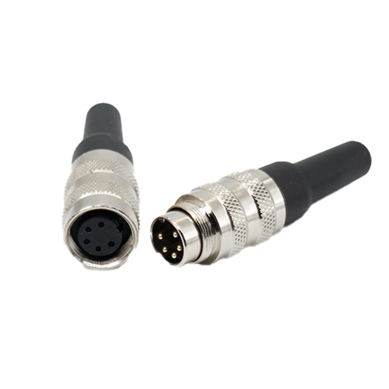
After the drawing review, arrange a fit check with the actual retained part under the equipment's approved maintenance procedure. Unexpected resistance, incomplete coupling or uncertain key alignment is a reason to stop and recheck the identity. Do not use tightening force to overcome an unexplained mismatch.
Record what was checked: the two part numbers, drawing revisions, installed clearance and wiring verification. A successful mechanical fit does not establish the pin functions or environmental performance. Resolve each required condition before the equipment returns to service.
If the retained half cannot be identified or the supplier cannot support the proposed mating pair, consider a reviewed replacement of both halves. That changes the scope of the repair and may affect the panel and harness. Send KMYD the retained-part evidence and mark each dimension or circuit detail that remains unknown; the next useful result is a specific, checkable replacement proposal.



 Tel: +8619924482730
 Email: info@kmydconnector.com
 MP/WhatsApp: +8619924482730
 Manufacturer Address:Baoan District, Shenzhen City, Guangdong Province,China