M8 3 pin male PCB connector is a compact circular interface used in industrial devices that require reliable signal connection, limited panel space, and direct circuit board integration. It is commonly applied in sensor modules, remote I/O units, compact controllers, measuring instruments, and automation equipment where external cables need to connect securely to an internal PCB.Compared with cable-mounted connectors, a PCB mount M8 connector reduces internal wiring and creates a cleaner internal electrical structure. The straight male interface provides a threaded connection on the device side, while the rear PCB pins are soldered directly to the circuit board. For equipment manufacturers, this design helps simplify assembly, improve production consistency, and support compact enclosure layouts.

1. Definition and Design Scope
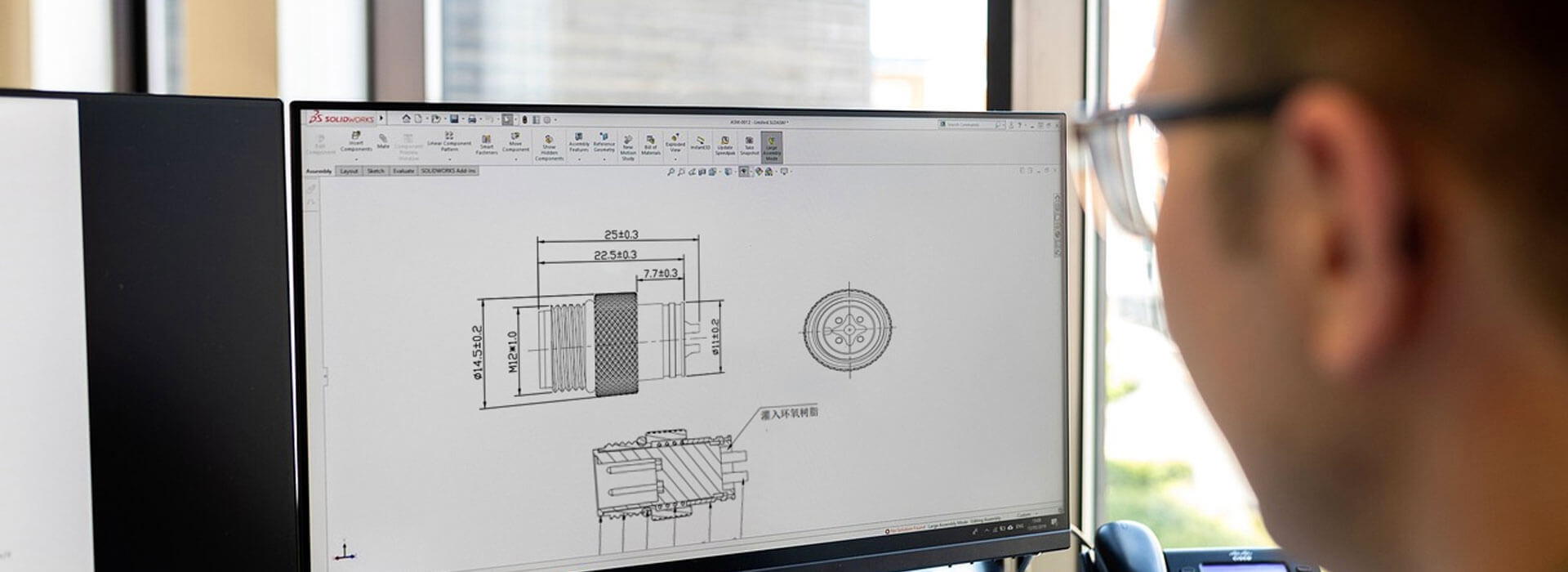
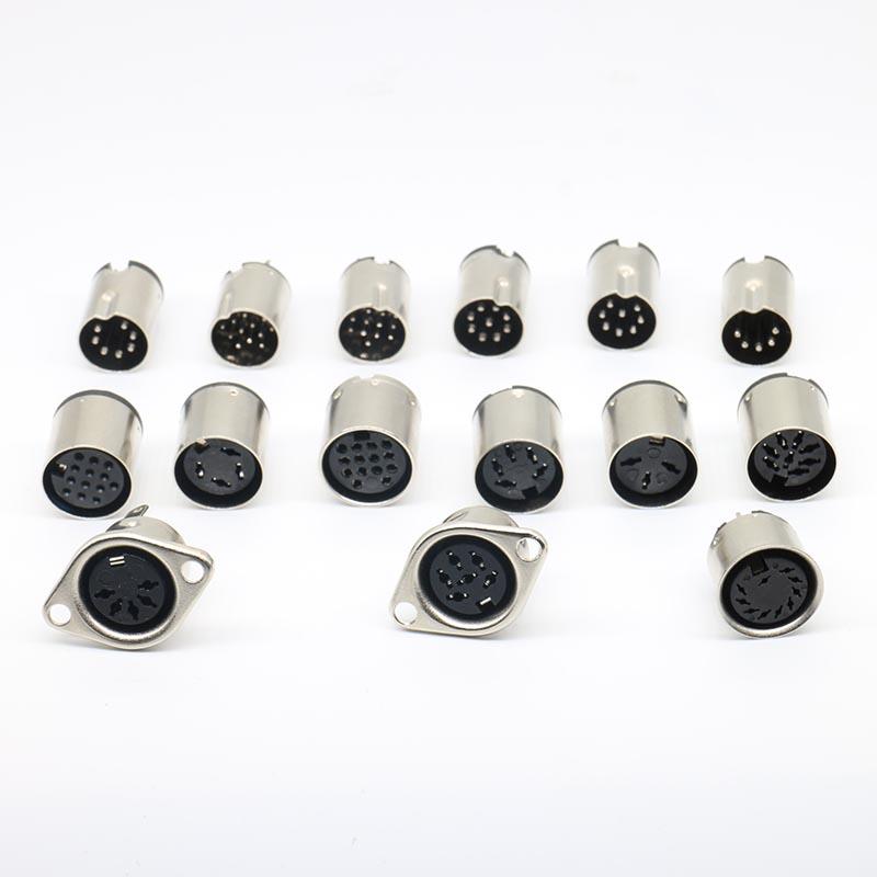
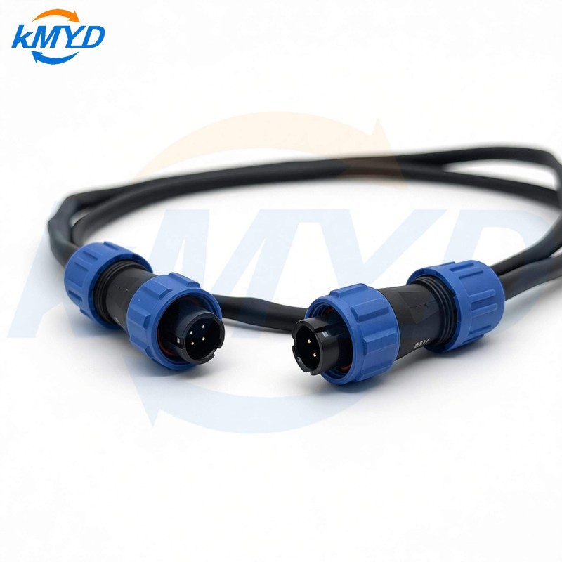
An M8 3 pin male PCB connector is a miniature circular connector with an M8 threaded male interface on the front and solder pins on the rear. The front side mates with a compatible female M8 cable connector, while the rear pins are inserted into the printed circuit board and soldered in place.
The 3 pin configuration is typically used for basic power and signal transmission. In many industrial systems, the three contacts are assigned to power positive, power negative, and one signal line. This makes the connector suitable for 3-wire sensors, simple actuator interfaces, signal input ports, and compact field device connections.
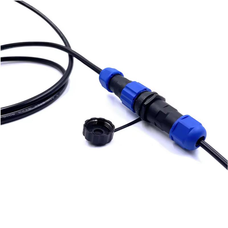
The M8 format is smaller than M12, which makes it useful when the housing is narrow or when several ports must be installed close together. At the same time, the threaded locking structure provides better mechanical security than many push-fit interfaces, especially in equipment exposed to vibration, movement, or repeated cable connection.
2. Structure and Interface Logic
The connector usually consists of a housing, threaded coupling area, male contact pins, insulating body, sealing components, and PCB solder terminals. In a straight PCB mount version, the mating direction and the soldering direction are aligned, which helps create a direct connection path from the external cable to the circuit board.
From an electrical design perspective, direct PCB soldering reduces the number of internal transition points. A cable-mounted connector may require extra wires, crimp terminals, or internal harness assembly. Each added connection point may introduce resistance variation, assembly error, or long-term reliability risk. A PCB mount connector removes many of these intermediate steps.
For compact industrial products, this is especially important. A remote I/O module, sensor hub, or small controller may have very limited internal space. By placing the connector directly on the board, the internal structure becomes easier to control, easier to assemble, and easier to inspect during production.
3. Flat-Edge PCB Mounting Value
A flat-edge or cut-edge M8 connector removes part of the circular outer profile. This may look like a small mechanical detail, but it is valuable in high-density panel design. When multiple circular connectors are arranged side by side, the outer diameter of each connector limits the minimum spacing between ports. A flat-edge body allows adjacent connectors to sit closer together.
In industrial I/O modules, narrow control boxes, and sensor distribution units, this can help increase the number of available interfaces without increasing the enclosure width. For example, a device panel that needs several M8 ports may benefit from reduced center-to-center spacing, allowing more ports to fit into the same front panel area.
The flat-edge design also helps with orientation control. When combined with positioning pins or a shaped panel opening, it can reduce the risk of rotation during assembly. This supports better alignment between the connector, PCB, and enclosure opening.
4. Key Specifications
| Parameter | Typical Specification | Design Meaning |
|---|
| Connector Type | M8 male PCB mount connector | Used as a device-side board-mounted interface |
| Pin Count | 3 pin | Suitable for basic power and signal wiring |
| Mounting Method | PCB solder type | Reduces internal wiring and improves assembly consistency |
| Orientation | Straight | Supports direct front-panel connection |
| Coding | A-coded | Commonly used for sensor and signal applications |
| Rated Voltage | 60V AC / 75V DC | Suitable for many low-voltage industrial circuits |
| Rated Current | 3A-4A | Supports common sensor and control signal loads |
| Contact Resistance | ≤10mΩ | Helps maintain stable electrical performance |
| Insulation Resistance | ≥100MΩ | Supports safe separation between conductive parts |
| Protection Rating | IP67 when properly mated | Suitable for dust and temporary water exposure in industrial environments |
5. Application Case: Industrial I/O Module
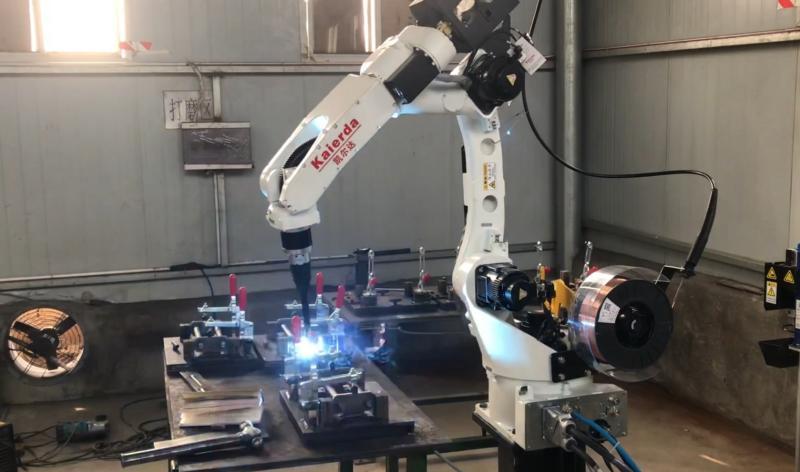
Industrial remote I/O modules often need several sensor interfaces on a narrow front panel. A flat-edge M8 PCB connector helps arrange multiple ports in a compact space while maintaining a sealed external connection. This is useful for distributed automation systems where the module is installed near machines, conveyors, robot cells, or production lines.
In a typical compact I/O module, the PCB carries signal processing circuits, power distribution, and several M8 connector interfaces. If each connector requires internal cable wiring, assembly becomes more complex and the enclosure may need additional internal space. PCB-mounted M8 connectors allow the interface ports to connect directly to the board, reducing internal wire routing and helping the module remain compact.
The 3 pin version is suitable for many standard sensor connections, including proximity sensors, photoelectric sensors, magnetic sensors, and other simple 3-wire devices. When the module requires higher signal density, multiple flat-edge connectors can be arranged close together to increase the number of available ports without significantly enlarging the product housing.

6. PCB Layout and Assembly Control
PCB layout is one of the most important design steps for this connector type. Engineers should check the recommended hole size, solder pad size, pin spacing, and positioning structure according to the connector drawing. If the connector includes locating posts, the PCB should reserve accurate positioning holes to prevent movement during soldering.
The flat-edge direction should also be confirmed during mechanical design. If the flat side is used to reduce connector spacing, its orientation must match the panel layout. Incorrect orientation may reduce the space-saving advantage or create interference with neighboring components.
Panel alignment affects both usability and sealing. The connector thread should be centered with the enclosure opening so that the mating cable can be tightened smoothly. Poor alignment may cause difficult mating, uneven sealing pressure, or reduced mechanical life.
Assembly control should also consider soldering temperature, connector verticality, mechanical stress, and inspection access. Because the connector is part of both the electrical circuit and the external mechanical interface, small dimensional errors can affect the final product more than ordinary PCB components.

7. Selection Checklist
| Selection Point | What to Confirm |
|---|
| Pin count | Confirm whether 3 pin is enough for the sensor, signal, or power circuit. |
| Coding | Use A-coded connectors for common sensor and basic signal applications. |
| Mounting type | Check whether the PCB solder pin layout matches the circuit board design. |
| Flat-edge direction | Match the cut-edge side with the panel spacing and adjacent connector layout. |
| Electrical rating | Confirm voltage, current, contact resistance, and insulation requirements. |
| Sealing requirement | Confirm IP67 performance when paired with a compatible mating cable connector. |
| Panel opening | Ensure the connector is centered with the enclosure opening for smooth mating. |
8. FAQ
What is an M8 3 pin male PCB connector used for?
It is used to create a compact board-mounted interface for industrial sensors, signal ports, remote I/O modules, controllers, and instruments.
Why choose a PCB mount connector instead of a cable-mounted connector?
A PCB mount connector reduces internal wiring, simplifies assembly, and creates a direct electrical connection between the external cable and the circuit board.
What does the flat-edge design do?
The flat-edge design reduces the connector side profile, allowing multiple connectors to be installed closer together on compact panels.
Is a 3 pin M8 connector suitable for IO-Link?
Many IO-Link applications use 4 pin connectors, so the required pin count should be confirmed according to the circuit and device specification.
Can this connector be used in waterproof industrial equipment?
Yes, when properly mated with a compatible cable connector and installed correctly in the enclosure, the connector can support IP67 protection for many industrial environments.
9. Conclusion
The M8 3 pin male PCB connector is a practical interface solution for compact industrial devices that require reliable signal connection, waterproof protection, and efficient board-level integration. Its straight PCB mount structure helps reduce internal wiring, simplify assembly, and improve production consistency.
The flat-edge housing design adds further value in high-density layouts, where multiple ports must be placed within a narrow enclosure. For remote I/O modules, sensor boxes, robot control equipment, compact instruments, and industrial controllers, this connector offers a strong balance of space efficiency, mechanical reliability, and electrical performance.
For engineers designing space-saving industrial interfaces, this connector provides a useful combination of compact size, direct PCB mounting, threaded mechanical security, and practical sealing performance.


 Tel: +8619924482730
 Email: info@kmydconnector.com
 MP/WhatsApp: +8619924482730
 Manufacturer Address:Baoan District, Shenzhen City, Guangdong Province,China