Din Circular Connector Types and Specifications Guide
Boosting Train Safety & Efficiency with Reliable Circular Connectors
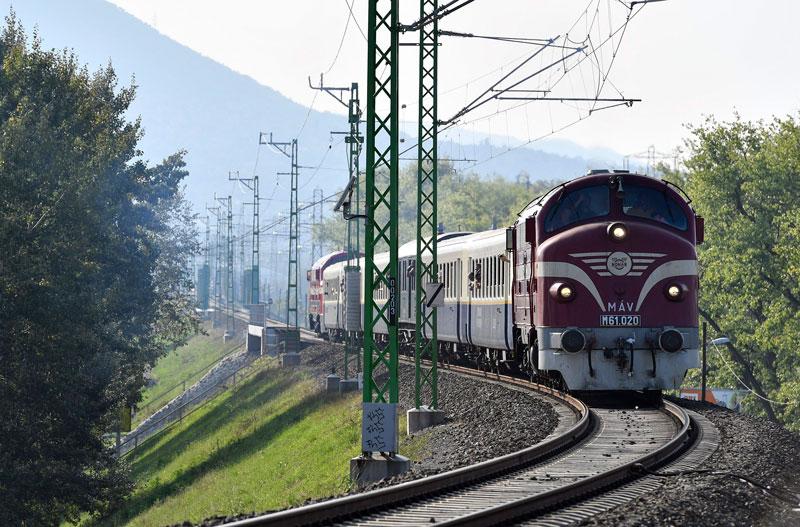
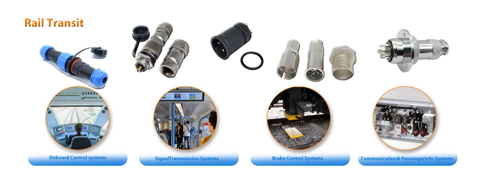
Modern railway operations depend on uninterrupted power, data, and signal transmission between critical train systems. From propulsion control to braking and passenger information systems, every connection must withstand vibration, temperature swings, and continuous duty cycles. This case outlines how a structured approach to connector selection supports safer, more efficient train operations.
Project Background & Industry Context
Rail operators and rolling stock manufacturers face increasing pressure to improve punctuality, reduce maintenance downtime, and meet stricter safety standards. In this environment, the choice of interconnect components directly affects system reliability. The project focused on upgrading the electrical interface between train control units and auxiliary systems to reduce connection failures and simplify maintenance procedures.
Interface & Environmental Requirements
The application required a circular connector capable of handling both power and signal lines within a single mating interface. Key specifications included a robust locking mechanism to prevent accidental disconnection under vibration, a protection rating suitable for dusty and humid trackside environments, and a cable entry range compatible with standard train wiring. The connector also needed to support repeated mating cycles for periodic maintenance without degradation in contact resistance.
Connector Solution & Configuration
After evaluating the electrical load, pin count, and mounting constraints, a circular connector series with a threaded coupling design was selected. The configuration included a panel-mounted receptacle on the equipment side and a field-wireable plug for the cable harness, allowing quick replacement without specialized tooling. The contact arrangement was verified against the train's wiring diagram to ensure correct keying and polarity, preventing mismating during installation.
Verification, Commissioning & Delivery Process
Before full deployment, sample connectors were subjected to mechanical and electrical checks, including insertion force, contact resistance measurement, and a trial mating with the actual cable assembly. During commissioning, the connectors were installed on a test bench and cycled through simulated vibration and temperature conditions. The delivery process included a documented inspection report and a visual check of each unit before shipment, ensuring that the connectors met the specified tolerances and surface finish requirements.
Verified Results & Operational Impact
The selected connectors provided a stable, low-resistance connection throughout the validation phase. The threaded coupling reduced the risk of loosening under dynamic loads, and the field-wireable design shortened replacement time during maintenance windows. While specific customer feedback and long-term field data are not available for publication, the engineering verification confirmed that the connector configuration meets the stated electrical and environmental requirements for this railway application.
For engineers evaluating similar interconnect challenges, the key decision factors are the mating cycle requirement, the cable entry range, and the environmental protection level. A clear specification of these parameters helps avoid mismatched components and ensures reliable long-term operation.
To explore suitable connector series for railway or industrial applications, review the 12G Series Circular Connectors or consult the Din Circular Connector Types and Specifications Guide for selection criteria.
If you have a specific train system interface to discuss, please use the inquiry form or contact us via WhatsApp to share your electrical load, pin count, and environmental requirements.




 Tel: +8619924482730
 Email: info@kmydconnector.com
 MP/WhatsApp: +8619924482730
 Manufacturer Address:Baoan District, Shenzhen City, Guangdong Province,China