

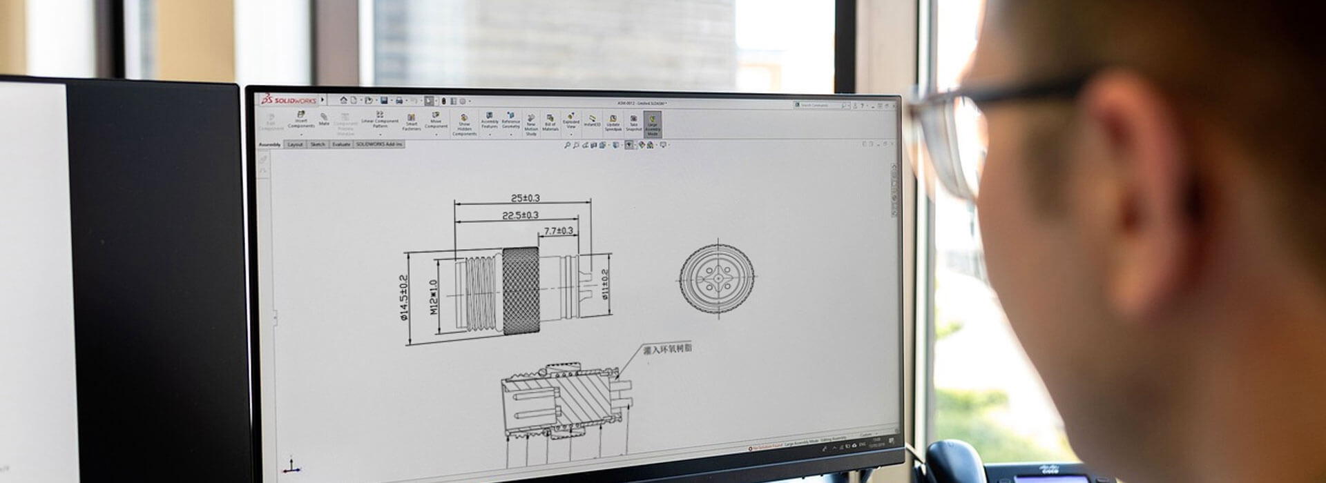
Choose a 50 ohm or 75 ohm BNC connector to match the specified impedance of the equipment and coaxial cable. Both values occur within the BNC family, so a connector that attaches to the socket is not enough to approve a replacement. Before ordering, identify the equipment port, cable part number, operating frequency or video format, and required mounting arrangement. Then ask for a part-specific drawing and electrical specification that cover that exact combination.
On this page
- Which impedance does your signal path require?
- A successful mechanical connection leaves an electrical question open
- Keep impedance and signal performance on separate lines
- The cable must fit the termination as well as the circuit
- Treat adapters and test leads as part of the decision
- Turn the comparison into an orderable specification
Which impedance does your signal path require?
Start with the equipment manual or interface specification. RF instruments and radio equipment often use 50 ohm connections; video and broadcast equipment commonly use 75 ohm connections. These are useful starting points, but the documented port requirement takes priority over the equipment's general description.
Swipe to view all columns →
| Ordering decision | 50 ohm BNC | 75 ohm BNC |
|---|---|---|
| Common starting point | RF links and test instrumentation | Video and broadcast signal paths |
| Required match | Equipment, cable and intervening components specified for a 50 ohm path | Equipment, cable and intervening components specified for a 75 ohm path |
| Separate checks | Frequency, power, termination and mechanical fit | Frequency or video format, cable pairing, termination and mechanical fit |
Check the complete route, including any patch lead, bulkhead feedthrough or adapter. Consistent impedance across the connector, cable and device helps control reflections. Record every component in the proposed path rather than approving only the connector at one end.
A successful mechanical connection leaves an electrical question open
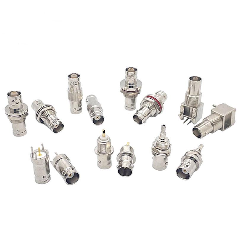
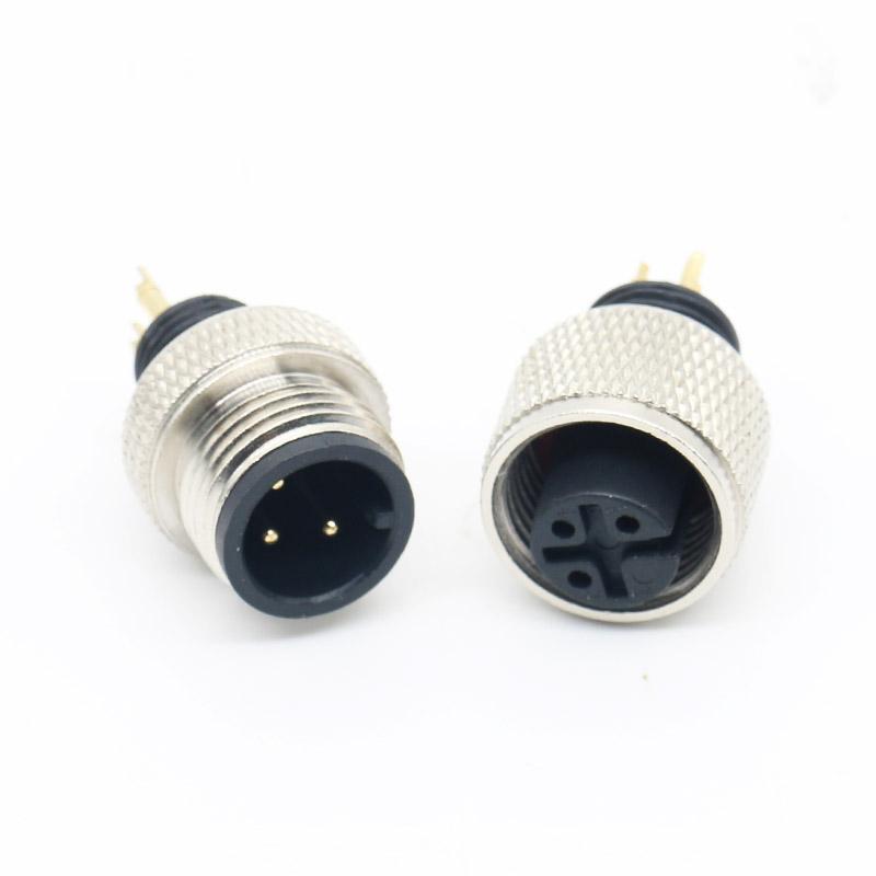
BNC identifies an interface family with bayonet coupling. It does not, by itself, specify a single impedance or frequency rating. A supplier photograph can help establish the body style, but it cannot replace the drawing and part number needed to select the electrical version.
Some 50 ohm and 75 ohm connectors can physically mate. Mixing them can still introduce an impedance discontinuity, increasing reflections and degrading the signal. Match connector impedance to the system even when a coupling locks into place.
Buying from an old sample alone leaves room for an undocumented substitution. Attach the approved drawing revision to the purchase order, and require any proposed alternative to be checked against the same requirements. The question is whether the replacement satisfies those requirements, not whether it resembles the sample closely.
Keep impedance and signal performance on separate lines
A 75 ohm marking does not establish support for every video format. Likewise, a 50 ohm marking does not establish the upper operating frequency of a connector or finished cable. Frequency capability depends on the actual design and configuration, so keep it separate from impedance in the specification.
For an RF connection, give the supplier the operating frequency range and applicable electrical limits. For a video link, specify the required interface format and the equipment at both ends. Ask for evidence tied to the offered connector and cable combination. Avoid accepting a family-level headline as approval for a particular assembly.
Agree how the sample will be accepted before the order is placed. Where return-loss measurements are required, specify the frequency range and limit on the test request. A vector network analyzer can be used for the measurement. Ask for the results for the offered assembly when they form part of your acceptance criteria.
The cable must fit the termination as well as the circuit
Identify the cable by manufacturer and part number where possible. A description such as “black coax cable” gives the supplier little basis for selecting a contact, ferrule or termination process. Include the cable drawing or datasheet when requesting a loose connector for an existing cable.
Check that the supplier's assembly instructions cover that cable. The termination must accommodate its center conductor, dielectric and shield construction, as well as the jacket. A nominal cable diameter alone does not describe all of those features. Connector selection also determines the applicable tooling and preparation instructions.
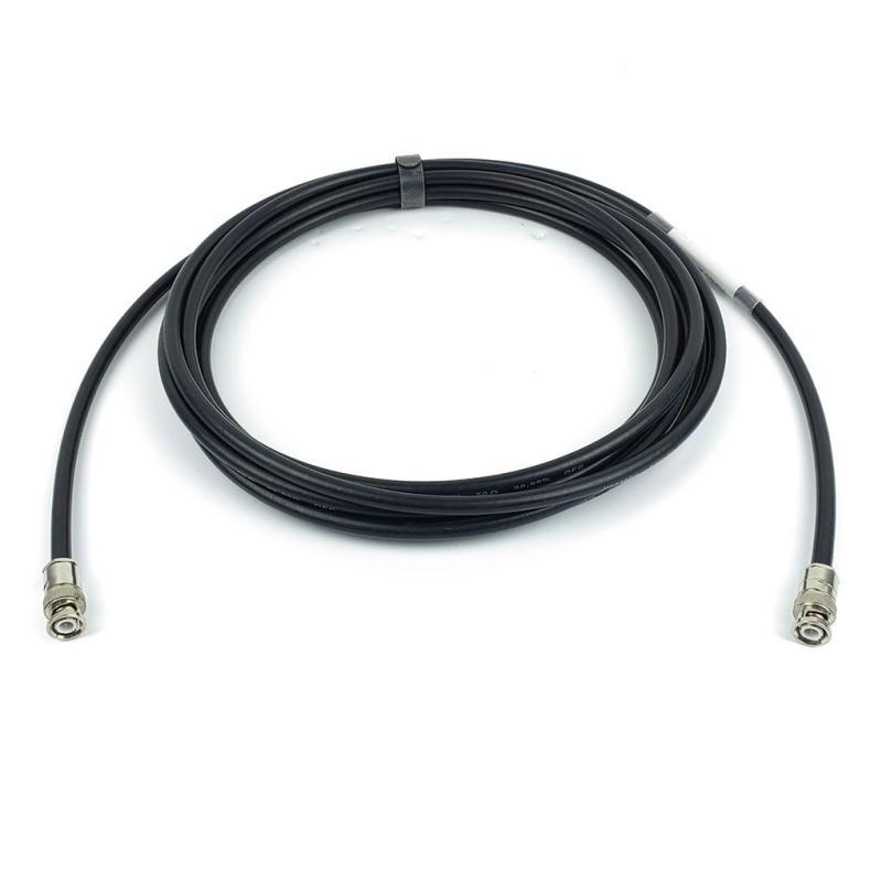
For a crimp version, obtain the specified preparation dimensions and tooling details. For a solder version, obtain its assembly instructions. Do not copy either process from a similar-looking part. If you are buying a completed cable, ask the supplier to identify the cable and both end connectors on the assembly drawing, so subsequent orders can refer to a defined build.
Treat adapters and test leads as part of the decision
An adapter's connector names do not describe all its electrical properties. Record its part number and function, especially where two instruments use different impedances. The correct arrangement depends on the measurement and the equipment; a change of connector interface alone is not a complete test specification.
For example, a 75 ohm measurement made with an RF analyzer may need a specific adapter and calibration arrangement. Follow the instrument's instructions for that measurement, including the stated reference plane. The appropriate setup depends on the instrument and accessories.
Ask whoever will accept the sample to review the planned measurement setup before testing. Include adapters and test leads in that review; otherwise, a result may be difficult to compare with the supplier's data.
Turn the comparison into an orderable specification
Consider these two illustrative inquiries. Each needs an attached specification, but both give the supplier a clearer starting point than “BNC male cable.”
- RF test lead
- “Please quote an assembly for the attached 50 ohm instrument interfaces and operating band. Identify both connector part numbers, the proposed coax and the assembly drawing. List any requirement that the offered build cannot meet.”
- Video patch lead
- “Please quote a 75 ohm assembly for the video interface specified in the attachment. Confirm the proposed cable, both end connectors and evidence for the required video format. Use the attached route drawing to review length and connector clearance.”
Use the following fields to make the quotation review concrete:
- Electrical requirement: impedance at each end, operating band or video format, and acceptance criteria.
- Interface and mounting: plug or jack, mating part, cable or panel mounting, and straight or right-angle body.
- Cable definition: cable part number, finished length with its measurement points, and termination or completed-assembly requirement.
- Installation constraints: available clearance, routing, environmental exposure and any project-specific qualification requirements.
- Supply record: offered part number, drawing revision, sample quantity, production quantity and agreed inspection documents.
KMYD's BNC RF connector page provides a starting point for a connector inquiry. Send the required impedance and cable details with the request, and ask for the exact proposed configuration to be identified. For a completed lead, the pre-wired BNC cable page is the corresponding inquiry route. Confirm the electrical requirements for the offered build before approving it.
Close the quotation review by checking that the sample, drawing and purchase-order description identify the same build. Any field still described as “to be confirmed” belongs on the review list before production approval.
Technical references: mixed-impedance connections; instrument-specific 75 ohm measurement guidance.


 Tel: +8619924482730
 Email: info@kmydconnector.com
 MP/WhatsApp: +8619924482730
 Manufacturer Address:Baoan District, Shenzhen City, Guangdong Province,China