SD20/SP20 Docking Connector
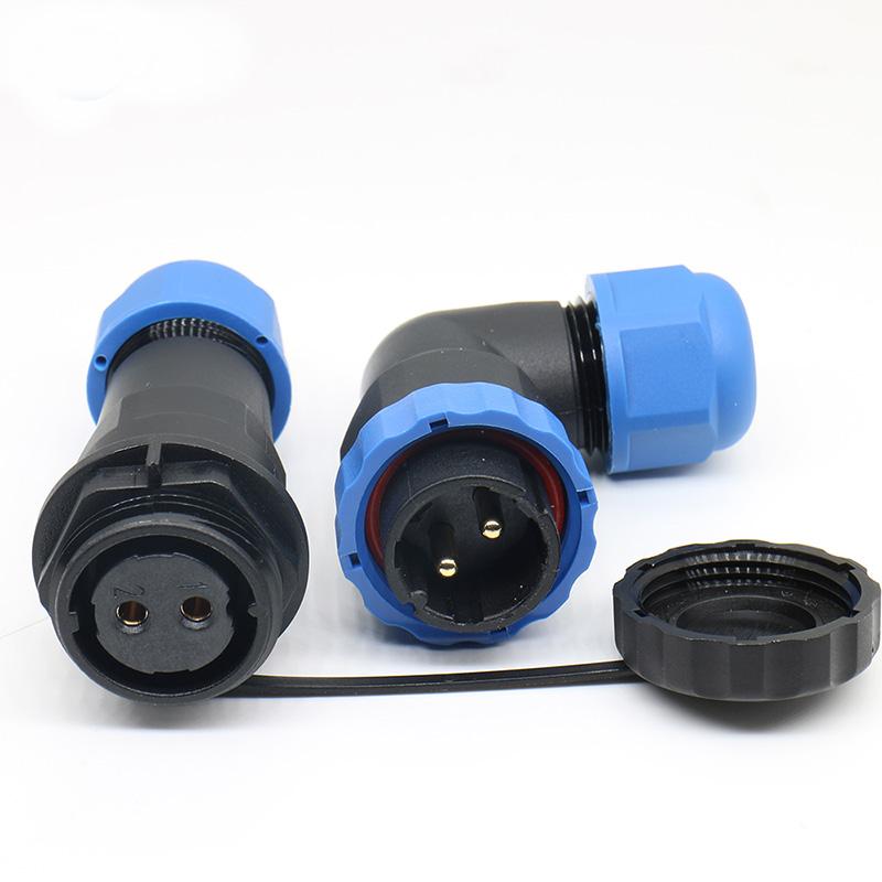
SP20/SD20 Right-Angle Docking Connector: Dimensions, Parameters, and Materials
This page provides the dimensional drawings, technical specifications, and material composition for the SP20/SD20 Right-Angle Docking Connector. It is intended for engineers and procurement professionals who need to verify mechanical fit, electrical ratings, and environmental suitability before integrating this connector into an industrial application.
What This Drawing and Specification Sheet Covers
The information presented here supports the evaluation of the SP20/SD20 right-angle docking connector for your specific mounting and cabling requirements. Use the dimensions and parameters below to confirm compatibility with your panel layout, cable entry direction, and operating environment.
-
Mechanical dimensions: Overall envelope, mounting hole pattern, and right-angle profile for space-constrained installations.
-
Electrical ratings: Current and voltage limits as specified for the contact arrangement.
-
Material components: Housing, contact, and sealing materials that define durability and environmental resistance.
-
Environmental protection: Ingress protection rating and operating temperature range relevant to your application.
Key Selection Criteria for the SP20/SD20 Right-Angle Connector
Before specifying this connector, verify the following points against your application requirements:
-
Mating interface: Confirm that the SP20 plug and SD20 socket versions match your cable and panel mounting needs. The right-angle configuration affects cable routing and clearance.
-
Electrical load: Check that the rated current and voltage meet your circuit demands, including any derating required at elevated temperatures.
-
Environmental exposure: Confirm the IP rating and temperature limits align with your installation environment, especially for outdoor or washdown areas.
-
Mechanical fit: Review the dimensional drawing to ensure the connector fits your enclosure cutout and that the right-angle cable exit does not interfere with adjacent components.
Understanding the Technical Parameters
The rated values shown in the drawing represent the connector's specified performance under standard test conditions. When applying the connector in demanding environments, consider the following:
-
Derating: Continuous operation at maximum current may require derating at higher ambient temperatures. Verify the thermal limits for your duty cycle.
-
Mating cycles: The specified number of mating cycles indicates expected mechanical endurance. Frequent connection and disconnection may require periodic inspection.
-
Cable range: Confirm that your cable diameter falls within the accepted range for the right-angle termination to ensure a proper seal and strain relief.
Material and Construction Notes
The material components listed in the drawing determine the connector's resistance to corrosion, chemicals, and mechanical stress. For applications involving vibration, salt spray, or chemical exposure, confirm that the housing and contact materials are suitable for your specific conditions.
Related Connector Options
If the SP20/SD20 right-angle docking connector does not fully match your mounting or performance requirements, review these related options from the same series:
-
SD20/SP20 Docking Connector – standard docking configuration for general-purpose applications.
-
SD20/SP20 Square Flange Connector – alternative panel mounting style with a square flange.
Next Step: Confirm Your Application Fit
To proceed with the SP20/SD20 right-angle docking connector, verify the dimensional drawing against your panel cutout and cable routing. If you need assistance confirming the electrical or environmental fit for your specific application, contact our engineering team with your requirements.




 Tel: +8619924482730
 Email: info@kmydconnector.com
 MP/WhatsApp: +8619924482730
 Manufacturer Address:Baoan District, Shenzhen City, Guangdong Province,China