12G Aviation Connectors with Multiple Core Count Options
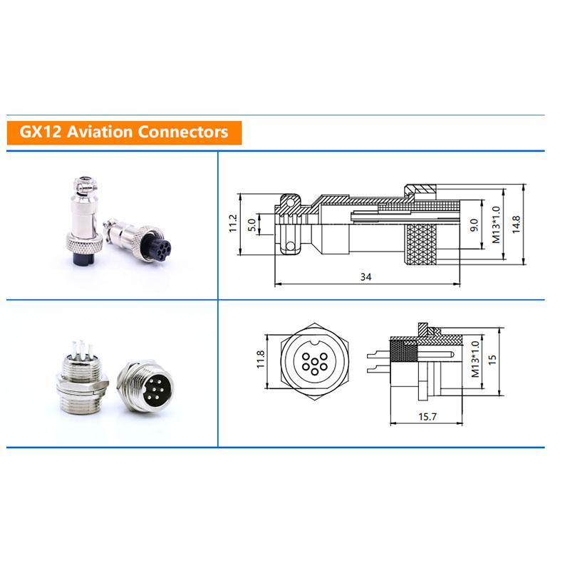
GX12 Aviation Connector Overview
The GX12 aviation connector series is designed for reliable signal and power transmission in industrial, instrumentation, and communication applications. This catalog presents the available configurations, core count options, and key technical parameters to help you match the right connector to your system requirements.
Each connector type is defined by its shell size, contact arrangement, and termination method. The following sections break down the material construction, environmental ratings, electrical limits, and installation considerations so you can evaluate suitability before specifying.
Core Count Options and Configurations
GX12 connectors are available in multiple core counts to accommodate different circuit requirements. The selection of core count directly affects the connector's outer diameter, contact spacing, and current-carrying capacity per contact.
- Common configurations include 2, 3, 4, 5, 6, 7, 8, 10, 12, and 19 contacts, depending on the series variant.
- Each core count option uses a specific contact layout and keying arrangement to prevent mismating.
- Verify the pin assignment diagram for your chosen configuration before ordering to ensure compatibility with your wiring scheme.
Material Construction and Durability
The housing and contact materials determine the connector's mechanical strength, corrosion resistance, and long-term reliability in demanding environments.
- Shell materials typically include zinc alloy or aluminum alloy with nickel or black anodized plating for corrosion protection.
- Insulation inserts are commonly made from high-temperature engineering plastics that maintain dimensional stability under thermal cycling.
- Contact materials are usually brass or copper alloy with gold or silver plating to ensure low and stable contact resistance.
Electrical Specifications and Performance Limits
Electrical ratings define the safe operating envelope for voltage and current. These values are rated under specific test conditions and may require derating at elevated temperatures or when multiple contacts carry current simultaneously.
- Rated voltage typically ranges from 250V to 400V AC/DC depending on the contact spacing and insulation material.
- Rated current per contact generally falls between 2A and 10A, with larger contacts supporting higher currents.
- Contact resistance is typically specified at or below 5mΩ to 10mΩ for gold-plated contacts.
- Insulation resistance is usually rated at 1000MΩ or higher at standard test voltage.
Note: Always consult the specific datasheet for your chosen core count and contact size, as electrical ratings vary between configurations.
Environmental Protection and Temperature Adaptability
GX12 connectors are designed for indoor and protected outdoor use. The degree of environmental protection depends on the mating condition and whether the connector is panel-mounted or cable-mounted.
- Standard GX12 connectors offer basic splash resistance when mated, but are not rated for continuous submersion.
- Operating temperature range typically spans -40°C to +85°C, with some variants extending to +105°C depending on insulation material.
- For applications requiring higher ingress protection, consider connectors with IP67-rated sealing or use protective covers when unmated.
Termination Methods and Installation
Termination style affects assembly time, serviceability, and field repair options. Choose the method that matches your production volume and maintenance requirements.
-
Soldering: Common for permanent installations where vibration is minimal and rework is unlikely.
-
Crimping: Preferred for production environments where consistent termination quality and repeatability are required.
-
Screw terminals: Suitable for field wiring and applications requiring periodic disconnection and reconnection.
Panel-mount versions use a threaded coupling nut for secure mating, while cable-mount versions are available with straight or right-angle cable entry options.
Selecting the Right GX12 Connector
To choose the correct connector for your application, evaluate the following parameters against your system requirements:
- Determine the number of circuits needed and verify the contact layout matches your wiring plan.
- Confirm the rated voltage and current meet or exceed your operating conditions with appropriate derating.
- Check the operating temperature range against your ambient environment and any self-heating effects.
- Select the termination method based on your assembly process and maintenance access.
- Verify the mounting style (panel or cable) and shell size fit your mechanical envelope.
Application Suitability and Limitations
GX12 connectors are well-suited for measurement instrumentation, communication equipment, industrial control systems, and test fixtures where reliable signal transmission is required. They are not intended for high-power distribution, continuous submersion, or applications with extreme vibration without additional strain relief and locking mechanisms.
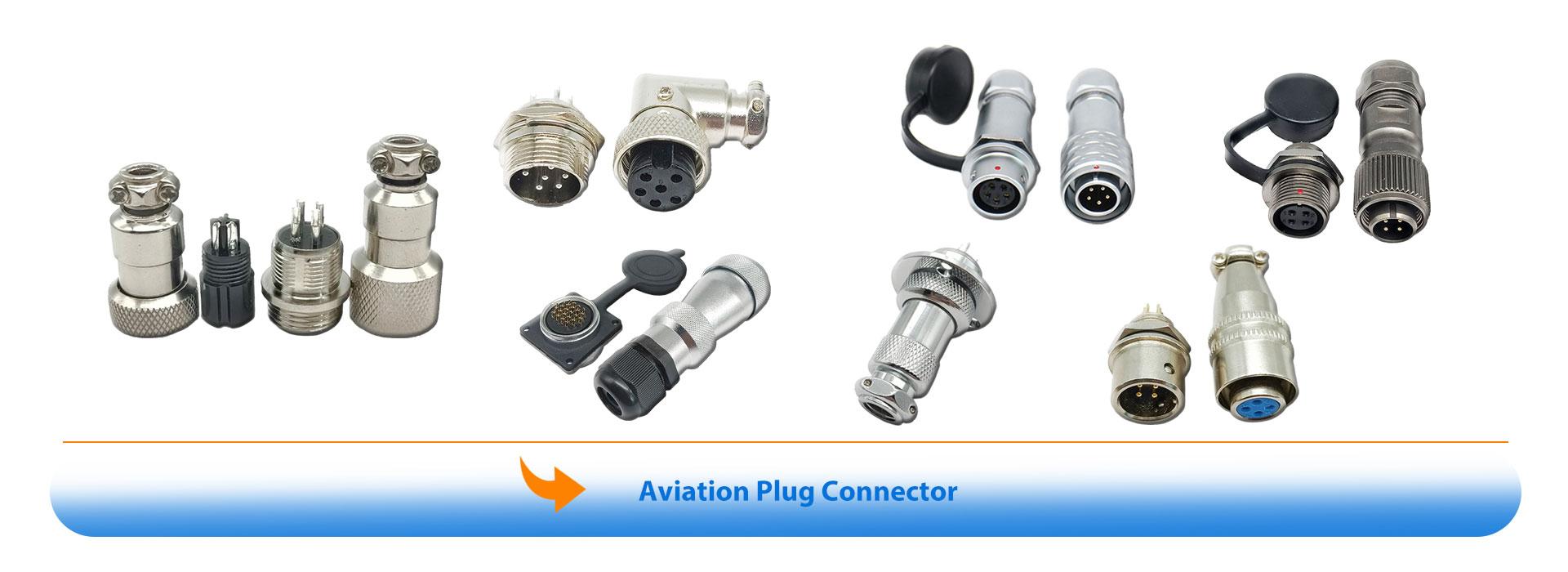
For applications requiring higher pin counts or different shell sizes, review the related aviation plug connector series to compare available options. If your project involves custom cable assemblies, consult the GX12 aviation female connector with custom cable assembly guide for integration considerations.
Next Steps for Specification
Before placing an order, prepare the following information to ensure accurate selection:
- Required core count and contact arrangement
- Rated voltage and current for your application
- Operating temperature range and environmental exposure
- Termination method (solder, crimp, or screw)
- Mounting style and cable entry orientation
- Any custom cable length or connector assembly requirements
Submit these details with your inquiry to receive a configuration recommendation that matches your technical and application needs.




 Tel: +8619924482730
 Email: info@kmydconnector.com
 MP/WhatsApp: +8619924482730
 Manufacturer Address:Baoan District, Shenzhen City, Guangdong Province,China